Smart Spring Calculator for Curved Spring Washers
Italic labels are optional or computed. Type any consistent set of values, including results like rate or stress. The solver finds the rest and shows how many degrees of freedom are left.
What Is a Curved Spring Washer?
A curved washer is a flat ring bent into a shallow arc across one diameter. It gives a light thrust load when it is pressed flat.
It is often used to take up axial end play in bearings, motors and other rotating parts. It is simple, compact and low in cost.
It works like a short beam supported at its ends and loaded across the ring. The rate is close to linear over most of its travel.
Wave washers spread the load over several crests and fit tight radial space. Belleville washers carry much higher loads. Finger washers use cantilever fingers. Each has its own calculator or design method.
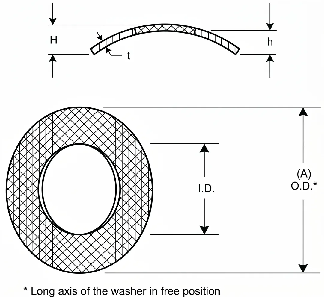 Curved Washer Dimensions
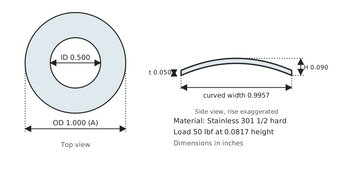
H is the free height. h is the travel, about H minus t. A is the OD along the long axis in the free position.
Curved Washer Dimensions
H is the free height. h is the travel, about H minus t. A is the OD along the long axis in the free position.
Design Considerations
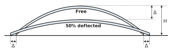
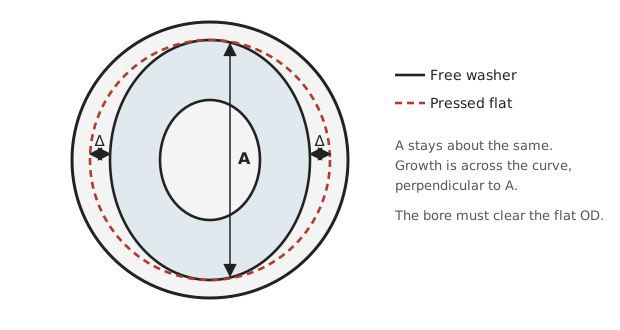
The washer gets wider as it flattens. Leave space for that growth in the direction perpendicular to the A dimension.
Use hard mating surfaces. Otherwise the washer corners can scrape or dig in.
The rate is about linear up to 80% of the available deflection. Past 80% the rate climbs and the load is well above the calculated value.
Load & Spring Rate
The load follows the simple beam equation with an empirical correction factor K.
Here OD is the outside diameter in the flat position. K comes from the chart below. It depends on the ratio OD/ID.
| Symbol | Meaning |
|---|---|
| t | Strip thickness |
| OD | Outside diameter, flat position |
| H | Free height |
| f | Deflection from free height |
| E | Young's modulus |
| K | Correction factor from the chart, set by OD/ID |
| P | Load |
Symbols used in the curved washer equations.
- These equations are approximate.
- They give good answers only for deflections up to 80% of h.
- The deflection f must also be less than one third of the OD.
- The rate is about linear up to 80% of the available deflection. Past that it rises and is well above the calculated value.
| OD / ID | K |
|---|---|
| 1.25 | 3.67 |
| 1.5 | 3.54 |
| 2.0 | 2.33 |
| 2.5 | 1.86 |
| 3.0 | 1.66 |
| 4.0 | 1.54 |
Values read from the digitized chart. The calculator interpolates between the charted points.
Stress & Curved Width
Stress is highest at the middle of the beam. It uses the same K as the load.
Check the stress at flat too. It is the deepest deflection the washer can see.
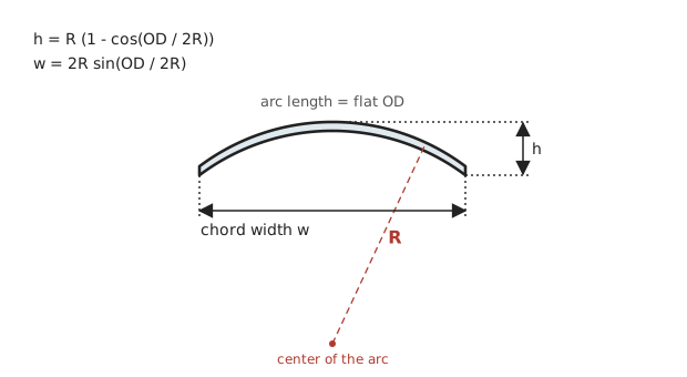
The flat diameters become chords of the arc once the washer is curved. Solve the arc radius R from the rise, then find each chord.
Choosing an Operating Stress
Allowable stress is a percent of tensile strength. It matches the values used for flat springs.
| Material | Stress-Relieved | With Favorable Residual Stress |
|---|---|---|
| Steels, alloy steels | 80% | 100% |
| Nonferrous alloys, austenitic steel | 75% | 80% |
Maximum recommended operating stress in static applications, as a percent of tensile strength.
Cyclic limits drop quickly as the required life goes up.
| Life (cycles) | Max Stress (% of tensile) |
|---|---|
| 104 | 80% |
| 105 | 53% |
| 106 | 50% |
For steel curved and wave washers such as AISI 1075. Assumes an ambient environment and no sharp bends, burrs or other stress raisers.
Tolerances & How to Specify
Dimensional tolerances are like those on flat springs. Tolerance only the dimensions that matter to the function.
Specify loads at a test height. Tighter tolerances are available for demanding jobs.
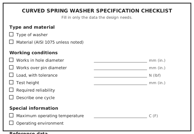
Fill in only the data the design needs.
- Type of washer and material
- Hole diameter and pin diameter it works in and over
- Load and tolerance at a test height
- Required reliability
- Description of one cycle
- Maximum operating temperature and environment
- Reference data: thickness, OD, ID and free height
Design Example
A curved washer must take up end play with a light load. It is 0.050 in thick, 0.090 in tall, with a 1.000 in OD and a 0.500 in ID. The strip is Stainless 301 1/2 hard, with a tensile strength of 150,000 psi. The load is about 50 lbf.
The diameter ratio OD/ID is 2.0. Figure RR-18 gives K = 2.33. With E = 28,000,000 psi, the rate is 6,015 lbf/in.
At 50 lbf the deflection is 0.0083 in, so the height is 0.0817 in. That is 20.8% of the 0.040 in travel, just inside the linear range.
Stress at 50 lbf is 69,830 psi, or 46.6% of tensile. The static limit for this material is 75%, about 112,500 psi.
Pressed flat, the load is 241 lbf and the stress is 336,000 psi. That is far over the limit. The washer needs a stop so it cannot be flattened.
| Item | Value |
|---|---|
| Rate | 6,015 lbf/in |
| Load / height / deflection | 50 lbf / 0.0817 in / 0.0083 in |
| Deflection, % of max | 20.8% |
| Stress at load | 69,830 psi (46.6% of MTS) |
| Load at flat | 241 lbf |
| Stress at flat | 336,000 psi |
| Weight | 0.0084 lb |
Values from this calculator for the example above.
Choosing Among Disc, Wave, Curved & Finger Washers
Belleville washers, wave washers, curved washers, finger spring washers, and stacked wave springs are all doing the same basic thing: a thin annular ring, formed out of flat, pushes back axially when compressed. What changes between them is how much force they give you, how much stroke they give you, and how much axial height that stroke costs. Picking the right one is mostly a matter of where your application sits on that trade-off, plus a couple of jobs (electrical contact, coil-spring-like travel) that only one shape really covers.
The Belleville washer (see the Belleville washer calculator) sits at one extreme: for a given radial envelope and axial height, it delivers the most force of the five, at the smallest deflection per washer. Stacking trades some of that force back for more stroke, but a single disc is still the highest-force-density option here.
The curved washer, the subject of this calculator, sits at the other extreme. It's a single gentle curve rather than a true cone or wave, the simplest and cheapest of the five to produce, and by far the lowest-force option. It exists almost entirely to take up assembly slack: light bearing preload, anti-rattle, a small constant push against a race, nothing that needs real clamping force.
The wave washer (see the wave washer calculator), typically three waves around the circumference in a single turn, is a step up from the curved washer: more force for the same material, at a moderate deflection, still a fraction of a Belleville's force density. It's the common drop-in for light-duty bearing preload where a Belleville would be overkill.
Nest wave washers crest-to-crest and you get a stacked wave spring: a compact substitute for a coil spring, with more total deflection and a more linear rate than any single washer in this family, in a much smaller radial envelope than a coil spring would need for the same force (though it does need more axial height than a single washer or a short Belleville stack).
The finger spring washer replaces the continuous wave or cone with cantilevered fingers. Force output is comparatively low, and the fingers are shaped to hold that force nearly constant across the working travel, which is exactly what steady electrical contact pressure needs through vibration and thermal cycling. If the joint also has to carry current or hold an EMI/RF shield path, this is usually the only one of the five actually built for that job.
These five don't have one shared, validated closed-form model the way the Belleville washer has DIN 2092, so this chart plots them as qualitative regions, not measured curves, positioned relative to each other by force density and available stroke for a roughly similar envelope. Treat it as a starting point for narrowing down a shape, then get real load-deflection data from the specific part or manufacturer.
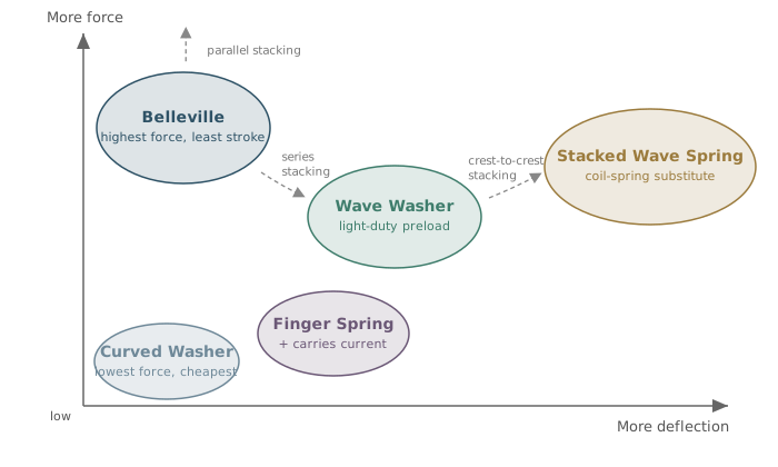
- Belleville washer: highest force, least stroke.
- Wave washer: light-duty preload, moderate stroke.
- Stacked wave spring: coil-spring substitute with the most travel.
- Finger spring: low force, steady contact, carries current.
- Curved washer: lowest force and lowest cost.
Static vs. Dynamic Stress Limits
A static spring is loaded once and held. Wave spring makers allow stress up to the full tensile strength here. The handbook is more cautious for stress-relieved parts.
A dynamic spring cycles. Keep operating stress at or below 80% of tensile. Go lower for long life.
Use the cyclic table in the design guide for a life target. Stress range matters more than the peak alone.
| Use | Limit (% of minimum tensile) |
|---|---|
| Static, published wave spring guidance | up to 100% |
| Static, handbook, steel, stress-relieved | 80% |
| Static, handbook, nonferrous or austenitic, stress-relieved | 75% |
| Dynamic, published wave spring guidance | 80% or less |
| Cyclic, handbook, 104 / 105 / 106 cycles | 80% / 53% / 50% |
The calculator uses the handbook static values (80% or 75%). That is the cautious choice.
Deflection Range & Load Accuracy
The calculated rate is linear through the first 80% of the available deflection. Past 80% the real load runs well above the calculated load.
This calculator flags anything outside 20% to 80%. The equations are only good while the deflection stays under one third of the OD.
Free height is the height with no load. Work height is the height at the specified load. Give the load at the work height on the drawing.
Tolerance the load at that height. Height alone is a poor way to hold load.
A Japanese spring maker gives the same beam equation with a load correction coefficient K1. It takes K1 as one minus the diameter ratio ID/OD.
K1 plays the part of 1/K in the handbook equation. At OD/ID = 2 it gives a rate about 16% above the handbook value. The same maker notes that the real load curve is a curve, not a straight line.
- The straight lines are calculated. The dotted curve is a typical real curve, drawn to show the trend. It is not measured data.
- Past 80% of travel the real load rises above the line.
- Your design replaces the example once it is fully defined.
Room to Expand
The flat OD is the length of the arc. Across the curve, the washer is a little narrower than that.
As the washer flattens, the width across the curve grows back to the flat OD. So the growth in that direction is the flat OD minus the curved width.
For the design example, wout is about 0.9957 in. The total growth is about 0.0043 in.
The long axis A stays about the same length. The growth is across the curve, perpendicular to A. Leave room for it and check with a test part.
Presetting & Residual Stress
Presetting compresses the part past its yield point once. The part keeps a small permanent set. It also keeps a helpful residual stress.
That stress opposes the working stress. The part carries more load and lasts longer in fatigue.
The handbook lists 100% of tensile for steel with favorable residual stress. It lists 80% without. Parts that are only stress-relieved get the lower value.
Presetting is a maker process. Ask for it on the drawing. Say how far and how many times.
Fatigue, Temperature & Relaxation
Life falls as the stress range rises. Cut the range and life goes up fast.
Raise the minimum load. That narrows the swing. It works for both wave and curved parts.
Burrs, sharp edges and surface flaws start cracks. Ask for clean edges.
The handbook gives a modified Goodman diagram for steel at HRC 47 to 49. The lines are for 106 cycles.
Reduce the values 10% for 107 cycles. Increase them 20% for 105 cycles.
Thin strip does better in fatigue. Plot the higher stress against the lower stress. A point under the line lasts longer than the line's life.
Heat lowers strength and modulus. The rate drops. The part can also relax and lose load over time.
Hard-temper wave springs are quoted to about 700 °F. Check the material you pick. Some alloys go much higher.
Load and travel needs often force a design to accept a little set. Plan for some load loss over life. Test at the real temperature.
Materials & Selection
Carbon steel and 17-7 stainless are the usual starting points. They are stocked and cost less.
Makers also offer many other alloys. Examples are Inconel X-750 and Elgiloy for harsh service.
Start with the environment. Then the life target. Then the budget.
- Corrosion or wet service: stainless or a nickel alloy
- Heat: a nickel alloy or 17-7 stainless
- Electrical or nonmagnetic parts: beryllium copper or phosphor bronze
- Low weight: titanium
| Material | E (Mpsi) | Density (lb/in³) |
|---|---|---|
| Medium carbon 1050 | 30.0 | 0.284 |
| 17-7 stainless CH900 | 29.5 | 0.282 |
| Stainless 301, 302, 304, 316 | 28.0 | 0.286 |
| Chrome silicon | 30.0 | 0.285 |
| Inconel 718 | 29.0 | 0.307 |
| Monel 400 | 26.0 | 0.300 |
| Beryllium copper | 18.5 | 0.300 |
| Phosphor bronze | 15.0 | 0.300 |
| Ti-15-3-3-3 | 15.0 | 0.174 |
Values from the calculator's material list. Modulus sets the rate. Density sets the weight.