4-20mA Current Loop Explained: 2-Wire, 3-Wire, 4-Wire, and Building a Loop Driver
What Is a 4-20mA Current Loop?
A 4-20mA current loop is a way of sending an analog measurement (pressure, level, temperature, flow) as an electrical current instead of a voltage. A transmitter (the field sensor) regulates how much current flows around a closed loop of wire, and a receiver (a PLC, DAQ, or indicator) reads that current and converts it back into an engineering value.
0% of the measured range is represented by 4mA, and 100% is represented by 20mA. A pressure transmitter scaled 0–100 psi, for example, outputs 4mA at 0 psi, 12mA at 50 psi, and 20mA at 100 psi. A straight linear relationship.
Current is identical everywhere in a series loop, no matter how long the wire run is or how much resistance the wire itself adds. A voltage signal droops over long cable runs; a current signal doesn't. The receiver sees the same milliamps whether the transmitter is 10 feet away or 2 miles away.
Starting the "zero" of the scale at 4mA instead of 0mA is called live zero. It means a dead loop (0mA) is instantly distinguishable from a valid reading of the minimum value. A broken wire, disconnected sensor, or dead power supply reads as 0mA, an obvious fault, rather than looking like a legitimate "zero" measurement.
2-Wire (Loop-Powered / Passive)
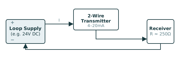 2-Wire Loop-Powered Transmitter
Only two wires total. The same pair carries power into the transmitter and the 4-20mA signal back out.
2-Wire Loop-Powered Transmitter
Only two wires total. The same pair carries power into the transmitter and the 4-20mA signal back out.
The transmitter is powered entirely by the loop current itself. The same two wires that carry the 4-20mA signal are the only connection to the device. This is the classic field-instrument pattern: a PLC or DCS supplies loop power (often 24V), and the 2-wire sensor modulates its own current draw between 4 and 20mA.
The catch is a strict power budget. Whatever the transmitter's internal electronics (amplifier, reference, sensor excitation) consume has to come out of the same current that represents the signal. Since the signal floor is 4mA, the transmitter's own quiescent draw must stay comfortably below that.
Also called passive, because from the loop's perspective the transmitter behaves like a variable resistor. It doesn't supply its own loop voltage, it just controls how much of an externally-supplied current gets through.
3-Wire, Common Negative (Low Side)
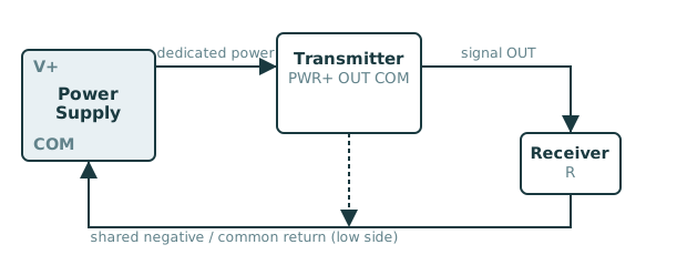 3-Wire, Common Negative
Power and signal each get a dedicated wire; the negative/common return is shared between them. The receiver's resistor sits between OUT and that shared COM line, hence "low side."
3-Wire, Common Negative
Power and signal each get a dedicated wire; the negative/common return is shared between them. The receiver's resistor sits between OUT and that shared COM line, hence "low side."
The transmitter now has its own dedicated power supply wires, so its internal electronics are no longer squeezed into the 4mA floor. It can draw as much current as it needs. The 4-20mA output becomes an active signal that the transmitter generates independently, rather than a current it merely limits.
Only three wires are needed because the power supply's negative rail and the signal loop's return share a single common wire. The receiver's load resistor sits between the transmitter's OUT terminal and that shared common, the low (negative) side of the circuit, which is where "low side" gets its name.
3-Wire, Common Positive (High Side)
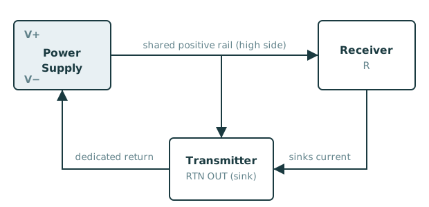 3-Wire, Common Positive
The shared rail is V+ instead of common. The transmitter's OUT terminal sinks current pulled through the receiver's resistor from that shared positive line, then returns it via its own dedicated wire.
3-Wire, Common Positive
The shared rail is V+ instead of common. The transmitter's OUT terminal sinks current pulled through the receiver's resistor from that shared positive line, then returns it via its own dedicated wire.
Mirror image of common-negative: here the positive supply rail is shared between the power circuit and the signal circuit instead of the negative rail. The transmitter's power-positive terminal and the top of the receiver's load resistor both connect to the same V+ line.
The transmitter's output terminal doesn't push current out. It sinks current, pulling it down through the receiver's resistor from the shared V+ rail, then returning it to the supply through its own dedicated return wire.
Functionally equivalent to common-negative from a measurement standpoint; the choice usually comes down to which noise/grounding scheme suits the rest of the system, or what a particular device model was built to expect.
4-Wire (Self-Powered / Active)
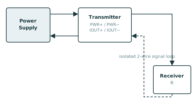 4-Wire Self-Powered Transmitter
Power and signal are two completely separate circuits with no shared wire. Two wires deliver power to the transmitter, and a fully independent two-wire loop carries the 4-20mA signal out.
4-Wire Self-Powered Transmitter
Power and signal are two completely separate circuits with no shared wire. Two wires deliver power to the transmitter, and a fully independent two-wire loop carries the 4-20mA signal out.
Full separation: two wires for power (e.g. a local 24V supply) and two wires for the 4-20mA signal loop, with no wire shared between the two circuits. There is no power-budget constraint at all. The transmitter's electronics draw whatever they need from the dedicated power input, completely independent of what current happens to be flowing in the signal loop.
This is the architecture that results from building a self-powered driver circuit (see the next card): the local supply, the regulating element, and the receiver's resistor form one series loop, while the control/logic electronics are powered separately and just tell that loop how much current to carry.
Building a Loop Driver
Consider a circuit supplied with 12–24V that needs to generate a 4-20mA signal for a downstream transducer or indicator to read, rather than living on someone else's bus. This is exactly the 4-wire / self-powered case above: the local supply, a regulating circuit, and the receiver's input resistance form one series loop.
Nothing is being measured with that current, it's only being driven. What matters is whether the driving circuit has enough voltage headroom to push 20mA through whatever resistance sits on the receiving end. If the actual device is unknown, 250Ω is the standard default (it's what turns a 4-20mA signal into a 1-5V reading inside many PLC/DAQ analog inputs). Add any wire resistance, which is usually negligible unless the run is very long or the wire gauge is small.
At 20mA into 250Ω, that's already 5V dropped across the load alone. With a 12–24V supply there is plenty of margin, even for a fairly sloppy driver circuit. The constraint only starts to bite with high load resistances on a low supply voltage.
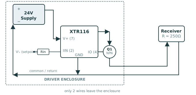 Self-Powered XTR116 Driver
The 24V supply, the XTR116, and Q1 all live together in one enclosure. Only two wires go out to the receiver. Current flows from the supply through Q1 (its collector tied to V+, base driven by IO) out to the receiver, through R, and back to the supply's negative terminal, one series loop. A small setpoint voltage through Rin into IIN sets how much of that loop current flows; GND shares the same return as the supply's negative terminal.
Self-Powered XTR116 Driver
The 24V supply, the XTR116, and Q1 all live together in one enclosure. Only two wires go out to the receiver. Current flows from the supply through Q1 (its collector tied to V+, base driven by IO) out to the receiver, through R, and back to the supply's negative terminal, one series loop. A small setpoint voltage through Rin into IIN sets how much of that loop current flows; GND shares the same return as the supply's negative terminal.
Circuit Options for Driving the Loop
An op-amp drives a BJT or MOSFET, with a precision sense resistor in the loop path feeding back to the op-amp's inverting input. The op-amp forces the voltage across the sense resistor, and therefore the loop current, to track a control voltage, regardless of load resistance changes within compliance. Works fine with a decent precision resistor and an appropriately-biased op-amp; fine for a one-off or hobby project.
A crude constant-current source built from a MOSFET, a resistor, and a Zener or reference diode can produce a rough 4-20mA signal. Good enough when precision doesn't matter; not something to trust for a calibrated measurement.
Purpose-built chips exist because doing this right (accuracy, temperature stability, protection against loop faults and reverse polarity) is fussier than the basic topology suggests. They split into two families that map directly onto the wiring taxonomy above:
- Self-powered / 4-wire drivers (TI XTR111/XTR116/XTR200, ADI AD5410/AD5412/AD5420/AD5422): these need their own supply rail, exactly the "building a loop driver" case shown in the XTR116 schematic above. They set the loop current directly; there's no power budget to worry about.
- Loop-powered / 2-wire DACs (ADI AD5421, TI DAC161S997/DAC161P997): these live entirely inside the 2-wire transmitter and must run all of their own electronics, plus whatever sensor front-end they're driving, off the same current they're outputting. This is the harder design problem, and it's the category that HART-compatible smart transmitters are built from.
These take an analog voltage setpoint, commonly driven from a microcontroller's DAC or a PWM output filtered into a clean DC level through an RC filter, since none of them decode digital PWM directly. Rin in the schematic above is exactly this kind of analog input.
| Part | Input | Package / Pins | Supply Voltage | Quiescent Current | Temp. Range | Status | Typical Use |
|---|---|---|---|---|---|---|---|
| TI XTR111 | Analog voltage (0–2.5V typ.) | 10-pin VSSOP / VSON | 7.5–44V | ≈1mA (ext. Q1 required) | −40°C to +125°C | Active | General-purpose driver; needs an external pass transistor like Q1 above for currents beyond the chip's internal handling |
| TI XTR116 (XTR115) | Analog voltage | 8-pin SOIC | 7.5–36V | ≈120–200µA | −40°C to +85°C | Active | Lower-power sibling of the XTR111 family, used in the schematic above; same external-transistor topology |
| TI XTR200 | Analog voltage | 10-pin WSON | 8–60V | ≈1mA | −40°C to +125°C | Active (newer) | Newer, higher-voltage evolution of the XTR111 with an integrated output transistor, current or voltage output, no external Q1 needed |
| ADI AD5410 / AD5420 | SPI (12-bit / 16-bit DAC) | 24-TSSOP, 40-LFCSP | 10.8–60V | ≈1.5–3mA | −40°C to +85°C | Active | Digitally-programmable current-out only version; setpoint comes over SPI instead of an analog pin |
| ADI AD5412 / AD5422 | SPI (12-bit / 16-bit DAC) | 24-TSSOP, 40-LFCSP | 10.8–40V | ≈1.5–3mA | −40°C to +105°C | Active | Same family plus a voltage-output mode and a HART coupling pin on the LFCSP package |
| TI XTR110, ADI AD693 / AD694 (legacy) | Analog voltage/current | Various DIP/SOIC (16–28 pin) | 4.5–36V (part-dependent) | ≈1–2mA | Industrial (−40°C to +85°C typ.) | Active, legacy design | Older analog-era self-powered drivers; still in production and still specified into designs, but superseded in new designs by the XTR/AD5410 families |
These sit inside a true 2-wire, loop-powered transmitter and set the loop current digitally, typically driven by a microcontroller that also runs the sensor and, in HART-capable designs, superimposes a digital communication signal on top of the 4-20mA current.
| Part | Input | Package / Pins | Loop Voltage | Quiescent Current | Temp. Range | Status | Typical Use |
|---|---|---|---|---|---|---|---|
| ADI AD5421 | SPI (16-bit, up to 30MHz) | 28-TSSOP, 32-LFCSP | 5.5–52V (loop-powered) | ≤300µA | −40°C to +105°C | Active | HART-compatible 2-wire smart transmitter DAC; the whole chip runs on current stolen from the loop |
| TI DAC161S997 | SPI (16-bit) | 16-pin WQFN | Loop-powered | <200µA class | −40°C to +105°C | Active | HART-ready loop-powered DAC; SPI setpoint plus built-in diagnostics (open-loop, short-circuit) |
| TI DAC161P997 | Single-Wire Interface (SWIF) | 16-pin WQFN | Loop-powered | <190µA | −40°C to +105°C | Active | Same family as the S997 but with a simplified one-wire digital protocol instead of full SPI, easier to isolate |
- Analog voltage input (XTR111/XTR116/XTR200, XTR110, AD693/AD694): the chip just reads a DC voltage on a pin. A microcontroller can drive this with a genuine PWM output run through a simple RC low-pass filter to turn it into a clean DC level, hence "PWM-compatible," but the chip itself never sees or decodes a PWM waveform.
- SPI input (AD5410/AD5412/AD5420/AD5422, AD5421, DAC161S997): a true digital serial interface. The setpoint is written as a binary word, giving full digital resolution (12- or 16-bit) with no analog filtering stage and no drift from an external RC network.
- Single-Wire Interface, SWIF (DAC161P997): a simplified one-line digital protocol, less flexible than SPI but easier to route through an isolation barrier since it's a single signal instead of SPI's clock/data/chip-select bundle.
Active vs. Passive, Sourcing vs. Sinking
"2-wire," "3-wire," and "4-wire" describe how many conductors run to the device. Active/passive and sourcing/sinking describe something different: which end of the loop actually supplies the voltage. These two axes usually line up but aren't strictly the same thing.
- Passive (sink) transmitter: relies on an external loop power supply, often at the receiver/PLC end, and just modulates how much of that externally-supplied current it lets through, like a variable resistor in series. This is the standard 2-wire, loop-powered pattern.
- Active (source) transmitter: has its own power and pushes current out onto the loop itself. 3-wire and 4-wire transmitters are active by nature, since they carry their own supply.
A circuit like the XTR116 driver above is electrically a 2-wire connection from the receiver's point of view (only two wires arrive at the receiver), but it's sourcing the loop voltage locally rather than relying on the receiver end to provide it. That makes it functionally a self-powered/active device wearing a 2-wire disguise, not the passive, loop-powered pattern that dominates commercial 2-wire transmitters.
Quick Reference
| Configuration | Wires | Power Source for Transmitter | Where the Load Resistor Sits | Key Constraint |
|---|---|---|---|---|
| 2-wire (loop-powered / passive) | 2 | Comes from the loop itself | In series, on the same 2 wires | Transmitter electronics must draw ≤ ~3.6mA |
| 3-wire, common negative (low side) | 3 | Dedicated power wires | Between OUT and the shared COM | Shares its negative return with the power supply |
| 3-wire, common positive (high side) | 3 | Dedicated power wires | Between the shared V+ and OUT | Shares its positive feed with the power supply |
| 4-wire (self-powered) | 4 | Fully separate supply | Fully separate 2-wire output loop | No power-budget constraint at all. This is the DIY driver case |