A seal is a device placed between two surfaces to prevent the flow of gas or liquid from one region to another. Seals are used for both static and dynamic applications. Static seals such as gaskets, bolt seals, back-up rings and sealants are used to prevent leakage through a mechanical joint when there is no relative motion of mating surfaces. Truly static seals are designed to provide a complete barrier to a potential leakage path. These seals are “zero leakage” seals (down to 10-11 scc/sec helium). In a truly static seal, the mating gland parts are not subject to relative movement except for thermal expansion and movement from the application of fluid pressure. Some static seals are designed to accommodate limited movement of the surfaces being sealed due to changes in pressure, vibration or thermal cycling, such as an expansion joint. These seals are sometimes referred to as semi-static seals.
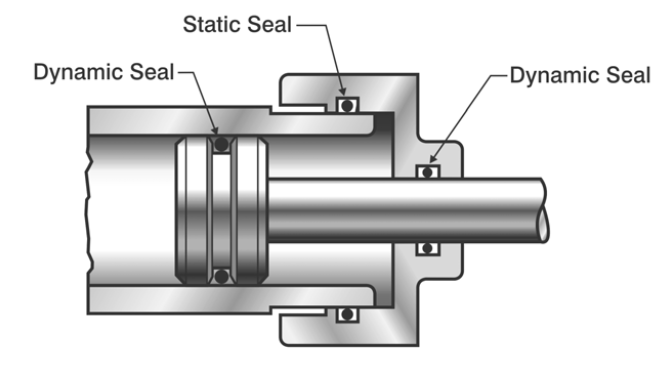
A dynamic seal is a mechanical device used to control leakage of fluid from one region to another when there is rotating, oscillating or reciprocating motion between the sealing interfaces. An O-ring can be used in both static and dynamic applications; however, the employment of O-rings as primary dynamic seals is normally limited to short strokes and moderate pressures. An example of static and dynamic seal applications is shown in Figure 3.1.
This tool estimates the failure rate of static seals and gaskets (O-rings, flange gaskets, bolt seals and back-up rings) using the leakage-based model from the Naval Surface Warfare Center Handbook of Reliability Prediction Procedures for Mechanical Equipment (NSWC-11, Chapter 3). A seal “fails” when its leakage exceeds what the application can tolerate, so the model multiplies a base failure rate by eight dimensionless factors covering pressure, allowable leakage, seal size, contact stress/hardness, surface finish, fluid viscosity, temperature and contamination.
Enter the seal geometry, material, fluid and operating conditions, then press Calculate. You get the predicted failure rate λSE in failures per million hours plus MTBF, ready as FMECA inputs.