Smart Spring Calculator for Belleville (Disc) Washers
| Parameter | Free | Load 1 | Load 2 | At Flat | Units |
|---|---|---|---|---|---|
| Applied Load | 0 | lbf | |||
| Outside Height | in | ||||
| Inside Diameter (est.) Same rigid-rotation estimate as Outside Diameter, applied to the bore edge: as the washer flattens, the ID shrinks slightly while the OD grows. Useful for a first check of shaft or pin clearance; verify against real parts for a tight fit. | in | ||||
| Outside Diameter (est.) As the cone flattens, the wall between ID and OD swings toward horizontal, so the OD grows and the ID shrinks slightly — it isn't a fixed dimension throughout travel. This estimate treats the wall as a rigid line rotating about the DIN 2092 circle of inversion (D0), a real published quantity, but the growth itself is a simplified geometric model, not an official DIN 2092 output. Useful for a first check of bore clearance; verify against real parts for a tight fit. | in | ||||
| Deflection | 0 | in | |||
| Spring Rate | lbf/in | ||||
| Stresses | |||||
| At Top ID (Sc) Compressive stress at the convex top corner near the inside diameter. Usually the largest-magnitude stress on the washer, and the one that governs static set (Reference Guide card 06). | 0 | psi | |||
| At Top OD Compressive stress at the convex top corner near the outside diameter. Smaller in magnitude than the inside-diameter compressive stress at Top ID, but still worth checking against the allowable. | 0 | psi | |||
| At Bottom ID (St1) Tensile stress at the concave underside near the inside diameter. One of the two locations that govern fatigue life in cyclic service. | 0 | psi | |||
| At Bottom OD (St2) Tensile stress at the concave underside near the outside diameter. For h/t above roughly 0.6 this tends to run higher than the inside-diameter tensile stress at Bottom ID, so check both in cyclic designs (Reference Guide card 04). | 0 | psi | |||
| Over Material Center Compressive stress at the theoretical center of inversion of the cross-section, roughly midway between the top and bottom surfaces. Rises linearly with deflection rather than following the same curve as the corner stresses. | 0 | psi | |||
STL export reflects whichever position tab (Free / Load 1 / Load 2 / At Flat) is selected in the 3D Model section below. STEP export and PDF reports are not yet built for this washer type.
What Is a Belleville Washer?
A Belleville washer — also called a coned-disc spring, cupped spring washer, or disc spring — is a shallow truncated cone of spring material that behaves as a spring when an axial load presses it flatter. As the cone collapses toward flat, the material stretches and compresses both radially and circumferentially, and that elastic strain is what stores the energy. The mechanism packs a coil spring's worth of spring action into a fraction of the axial length.
Because a single disc produces only a small amount of travel for its diameter, Belleville washers are rarely used one at a time in demanding designs — they are usually stacked, and the whole family of stacking arrangements (covered later in this guide) is really an extension of one washer's design math.
Two very different design goals both lean on this same part. The first is raw load capacity in a tight space: a Belleville stack can react a large axial force in an envelope far shorter than an equivalent coil spring, which is why the part shows up as stripper springs in stamping dies and as return elements in recoil mechanisms and pressure-relief valves. The second goal exploits the disc's non-linear load–deflection curve, which — for the right proportions — stays nearly flat over a wide part of its travel. That near-constant force is valuable in packing seals, machine-tool live centers, and clutch assemblies, where the clamping force needs to hold steady even as parts wear or shift with temperature.
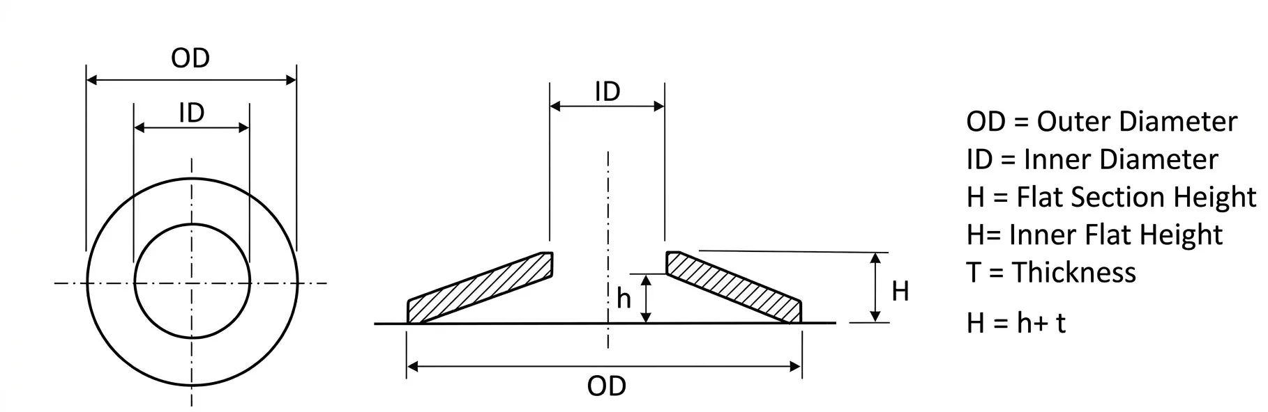 Belleville Washer Dimensional Terminology
Geometry & the Height-to-Thickness Ratio
Every Belleville washer is described by its outside diameter (OD), inside diameter (ID), thickness (t), and cone height (h) — the vertical rise from the bottom edge to the top edge measured before any load is applied. The overall height (H) is simply the cone height plus material thickness, H = h + t, and is the free height an assembler would actually measure with calipers.
The single most important shape parameter, though, is the ratio of these last two dimensions:
This one number governs whether the disc behaves like a stiff, nearly linear spring or like a device that holds an almost constant force over a wide range of travel — and, taken too far, whether it becomes bistable.
The second governing ratio compares the outside and inside diameters:
R is what every dimensionless factor in this guide is a function of — M, C1, C2, T1, T2, and the DIN 2092 K1–K4 coefficients (card 04) all depend on R alone, not on the absolute size of the washer. Discs proportioned near R ≈ 2 store the most energy per unit of material, which is why that value keeps coming up as a starting point (card 08).
A disc with a low h/t (roughly under 0.4) produces a load-deflection curve that is nearly a straight line — it acts much like a very stiff flat spring, well suited to applications that just need a large force from a small package and don't care about a flat load curve.
As h/t rises toward 1.41, the curve develops a broad, nearly horizontal plateau — for roughly the middle half of its travel either side of the flat position, load barely changes with deflection. This is the proportion designers reach for whenever the goal is a constant clamping force that shrugs off wear, thermal growth, or assembly tolerance.
Push h/t higher still, past about 2.83, and the curve stops being single-valued: once compressed beyond flat, the disc will not return to its original dome on its own — it has snapped into the opposite dish and needs an external force to pop it back. Unless a design intentionally wants that toggle action, h/t should stay below this threshold.
Mounting, Loading & Usable Deflection Range
When a Belleville washer is squeezed between two flat surfaces, the calculated load-deflection curve is only trustworthy across roughly 15% to 85% of the cone height h. Below 15%, seating effects and minor edge imperfections dominate; push past 85% and the load rises faster than the ideal-curve math predicts, because the contact geometry itself starts to shift.
Load has to be introduced uniformly around the full circumference at both the top and bottom edge — a few point contacts instead of a continuous ring will cock the disc and produce stresses and deflections nothing like the design calculation.
The corners where a Belleville washer contacts its mating surfaces matter more than they might appear to. A generously rounded edge removes active material and shortens the effective moment arm, which stiffens the disc and raises its rate. A sharp corner does the opposite for rate but concentrates stress right where fatigue cracks like to start — sharp edges buy a lower rate at the cost of cyclic life. Most designs land on a light break edge as the practical middle ground.
Some designs need a precisely controlled load right at, or even beyond, the flat position — for example a mechanism that must stay compact once fully seated. Ordinary flat-plate mounting cannot do this reliably, because as the disc approaches flat, the contact ring migrates and the effective moment arm collapses in an uncontrolled way. A support that locates the load at a fixed radius near the outer and inner edges, and that adds a positive mechanical stop, is needed instead. With that kind of support, the rate actually increases once the disc passes flat, since the moment arm keeps shrinking as travel continues.
 Mounting a Belleville Washer for Travel Past Flat
Some Belleville washers are manufactured with a small flat land ground onto the inner and/or outer edge rather than a knife-sharp corner. This controls exactly where the contact line sits, reduces local bearing stress against the mating part, and makes the effective moment arm more predictable. The trade-off is slightly less active spring material.
Stress Distribution & the Almen–Laszlo Method
Stress is far from uniform across a Belleville washer's cross-section. The highest-magnitude stress is compressive and occurs at the convex top corner near the inside diameter (Sc). Two tensile stresses develop on the concave underside: one at the inner edge (ST1) and one at the outer edge (ST2). For discs with h/t above roughly 0.6, ST2 tends to run higher than ST1. Cyclic designs should check the stress range at both bottom locations rather than assuming the inner edge always governs. See the "Which Point Governs" chart later on this card for exactly when each one does.
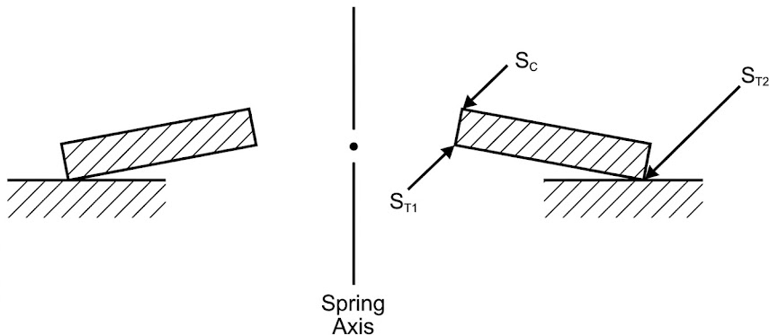 Critical Stress Locations
Each of the three stresses follows the same leading term as the load equation, with its own location-specific bracket:
Before the stresses, the same 1936 Almen and Laszlo analysis gives the load-deflection relationship itself, through a shared leading term and a location-specific bracket:
| A | O.D. / 2 |
| C1, C2 | compressive stress constants — function of R only |
| h | inside (cone) height |
| H | overall height |
| M | constant — function of R only |
| PF | load at flat position |
| R | O.D. / I.D. |
| Sc | compressive stress at convex I.D. corner |
| ST1 | tensile stress at concave I.D. corner |
| ST2 | tensile stress at concave O.D. corner |
| T1, T2 | tensile stress constants — function of R only |
M, C1, C2, T1, T2 are dimensionless factors that depend only on the diameter ratio R = OD/ID — Almen and Laszlo published them as charts rather than closed-form expressions. The later DIN 2092/2093 standard refines this same relationship with its own closed-form K1–K4 coefficients, which is the form most current disc-spring software actually computes with.
Whether ST1 (Bottom ID, DIN point II) or ST2 (Bottom OD, DIN point III) runs higher depends on both the diameter ratio δ = De/Di and the height ratio h0/t, not on h/t alone. Bauer's own catalog gives this exact boundary as a chart: below the lower line, Bottom ID governs; above the upper line, Bottom OD governs; in the gap between the two lines, both are close enough that either could be the worse one, so check both. This calculator's own fatigue-life estimate (card 06) sidesteps this chart entirely by just evaluating both locations directly and using whichever is worse, which is simpler and at least as conservative, but the chart below is useful for seeing at a glance why ST2 overtakes ST1 above roughly h/t = 0.6, as noted earlier on this card.
The Almen–Laszlo constants (M, C1, C2, T1, T2) above were originally published as charts, read by eye. DIN 2092 replaced them with closed-form coefficients K1–K3 that depend only on the diameter ratio δ = De/Di — this is the form this calculator's diameterFactors() function actually evaluates, and it's algebraically equivalent to the Almen–Laszlo constants above.
D0 is the diameter about which the cross-section effectively pivots as the washer deflects — this calculator's diameter-at-deflection estimate (ID/OD columns in the Load Positions table) uses it as a rotation center. K1 sets the overall load/stress scale; K2 and K3 split that scale between the four DIN cross-section points (I, II, III, IV — this calculator's Top ID, Top OD, Bottom ID, Bottom OD).
Stacking — Series, Parallel & Combined Arrangements
Nesting identical washers all facing the same direction — a series stack — multiplies deflection by the number of washers while the load stays that of a single disc. Nesting washers in alternating pairs, concave against concave and convex against convex — a parallel stack — multiplies load by the washer count while deflection stays that of one disc. Series and parallel groups can be combined to reach a target load and deflection that neither arrangement alone would hit.
Both stacking arrangements exhibit hysteresis from friction between adjacent washer faces — worse in parallel stacks, where more surface area slides against itself, than in series stacks. Lubricating the mating faces reduces this friction, though the resulting energy loss is not purely a downside: it damps vibration passing through the stack.
A stacked assembly must be guided, either over a pin or inside a bore, or the discs will walk sideways under load. Guide surfaces should be hardened to at least HRC 50 to resist wear from the sliding washer edges, and diametral clearance between the washer bore/OD and its guide should run around 1.5% of the relevant diameter — tight enough to control position, loose enough not to bind as the stack deflects.
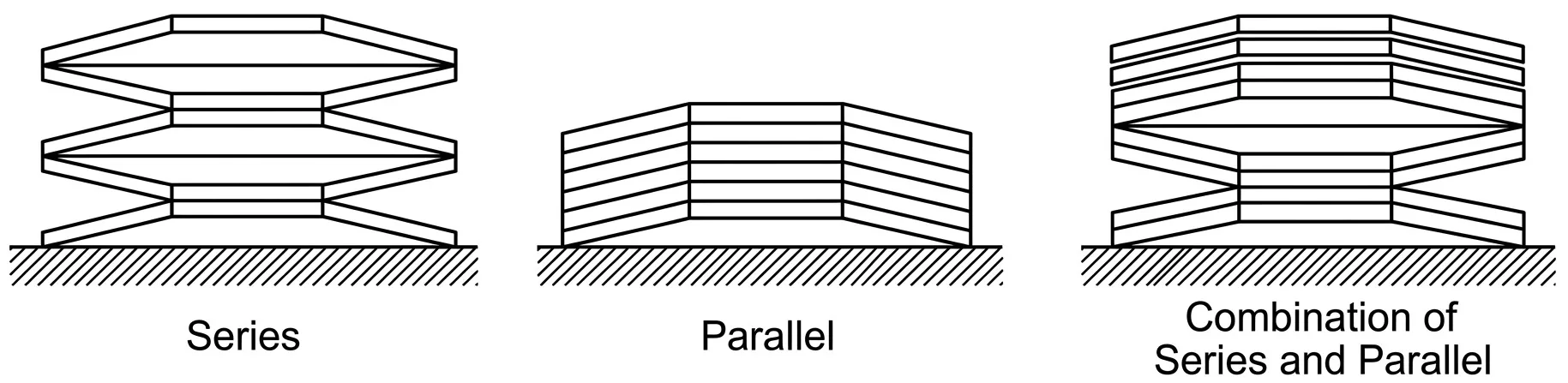 Series, Parallel & Combined Stacks
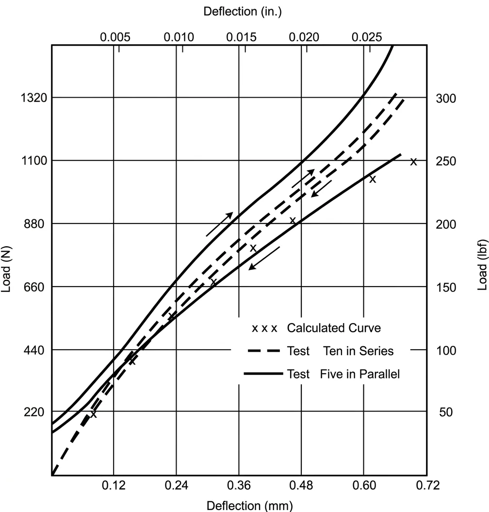 Hysteresis in Stacked Belleville Washers
For i groups arranged in series, each group being n washers nested in parallel (t → t′ for contact-surface washers in every formula on this card):
Each arrangement above just stretches one washer's own force-deflection curve along one axis: series stacking (larger i) stretches it sideways (more deflection, same force), parallel stacking (larger n) stretches it vertically (more force, same deflection), and a combined stack does both at once. All four schematics below are drawn to the same pair of axes so the stretching is easy to compare directly.
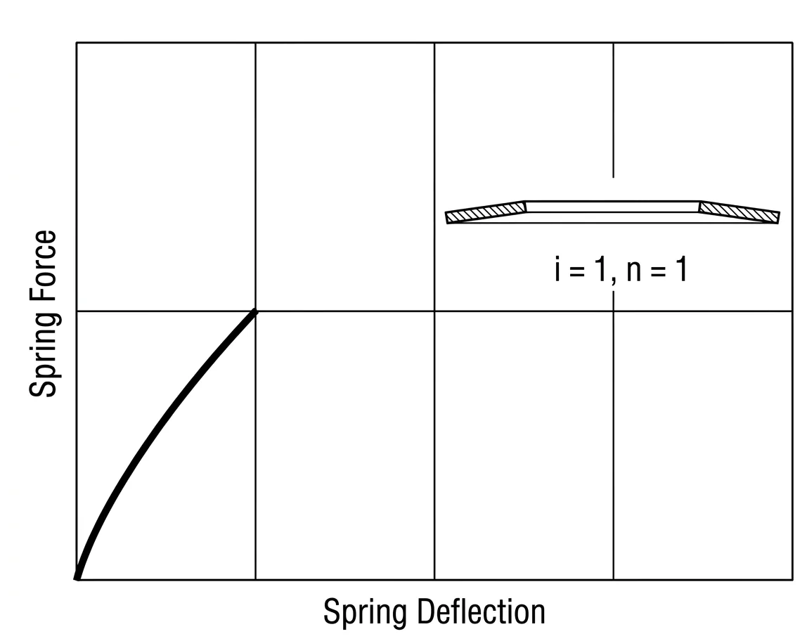 Single Washer (i=1, n=1)
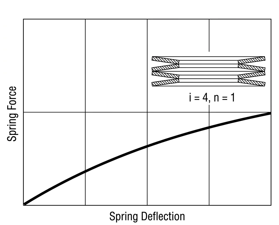 Series Stack (i=4, n=1)
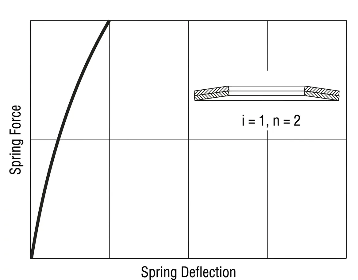 Parallel Bank (i=1, n=2)
 Combined Stack (i=4, n=2)
A single disc spring's curve is linear-to-degressive, never progressive (card 02), and stacking alone doesn't change that shape — it only stretches it, per the four schematics above. Getting a genuinely progressive (rising-rate) response out of disc springs takes splitting the stack into sub-groups that "lock out" one at a time as deflection increases, so the remaining active groups get progressively stiffer. Two ways to build that:
Different maximum force per group. Arrange series groups x, y, and z with the same washer count but different individual load ratings. All three groups deflect together at first (combined curve x+y+z), but group x flattens out (reaches its own load-to-flat) at force Fx and stops contributing further deflection, leaving only y+z active and stiffer. Group y flattens next at Fy, leaving z alone to carry the rest of the travel at its own, steeper rate.
The same lockout effect can also be built with identical washers by varying the number of parallel washers per group instead of the individual washer rating — more washers in a bank means that bank reaches its collective load-to-flat sooner, so it's the bank size rather than the washer rating that staggers the lockouts.
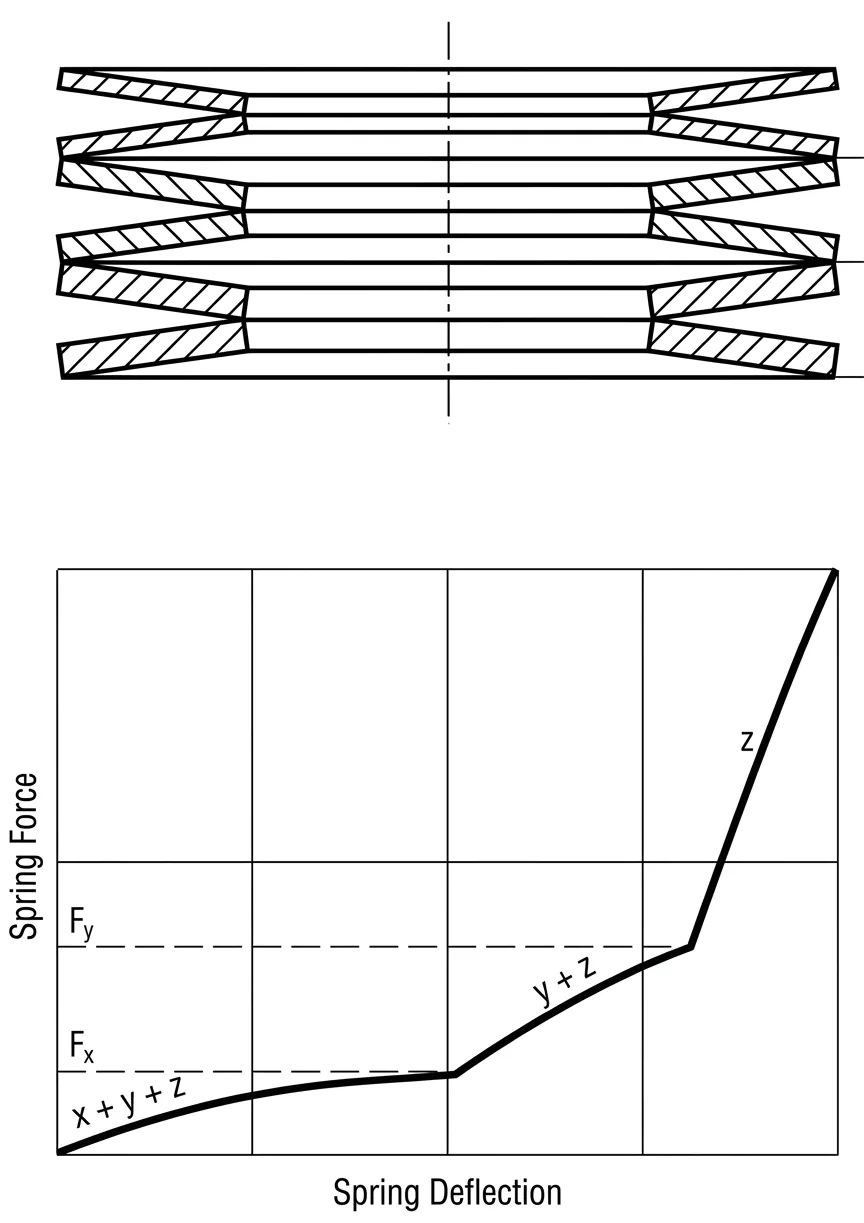 Progressive Stack via Different-Force Series Groups
Mechanical stops of different thicknesses. Rather than relying on groups flattening on their own, a stepped stop sleeve inside the guide can physically bottom out each section of the stack in sequence as the assembly compresses, engaging progressively stiffer sections on a schedule set by the sleeve's machined steps rather than by the springs' own load-to-flat points.
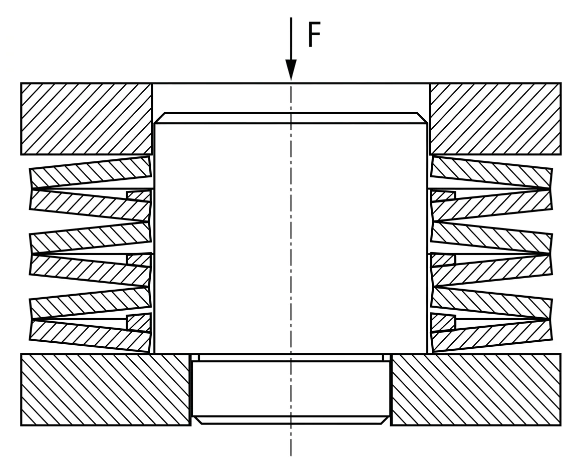 Progressive Stack via a Stepped Stop Sleeve
Three separate contacts generate friction in a real stack: (a) between the end washers and the compressing surfaces, (b) between adjacent washer faces in a nested/parallel group, and (c) between the washer bore/OD and its guide element. Friction (a)+(b) together raise the loading force and lower the unloading force relative to the frictionless calculation — this is the physical cause of the hysteresis loop shown above and in the chart further down this card:
Use the minus sign while loading, the plus sign while unloading. wM is the friction coefficient between nested washer faces; wR is the friction coefficient at the compressing-surface contact.
| Series | wM (inter-washer) | wR (end contact) |
|---|---|---|
| A | 0.005 – 0.03 | 0.03 – 0.05 |
| B | 0.003 – 0.02 | 0.02 – 0.04 |
| C | 0.002 – 0.015 | 0.01 – 0.03 |
Series A/B/C follow DIN 2093's geometry classes (roughly linear / moderately degressive / highly degressive, per card 02). Friction at the guide element itself (contact (c) above) isn't reliably predictable from geometry alone — it dominates in long stacks or stacks with many small groups, and grows with taper angle, so a guided long stack should be validated by test rather than by these formulas alone.
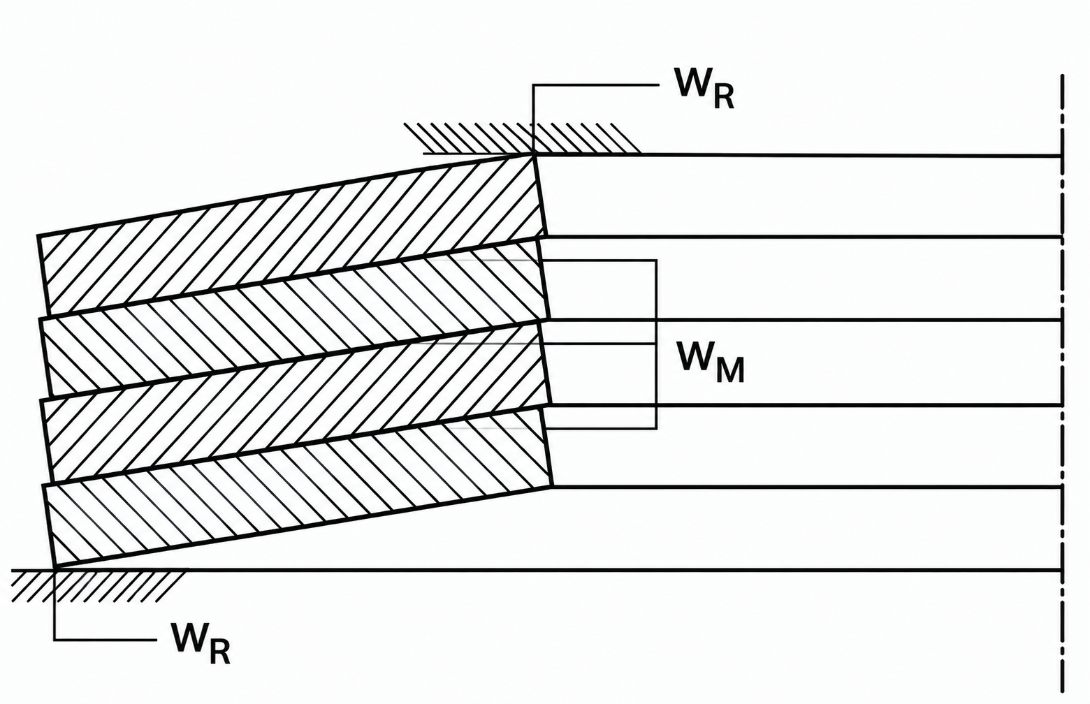 Friction Contacts in a Disc Spring Stack — wR (end) & wM (inter-washer)
Guide friction (contact (c) above) doesn't just cost force margin — it also means the individual washers in a long series stack don't all see the same stroke. Testing by Hertzer on 34×12.3×1.0 mm washers (l0 = 2.25 mm, 0.1 mm pretension + 0.5 mm working stroke per disc, stacks of i = 10/20/30) shows the washer nearest the moving end of the stack sees noticeably more stroke than the one nearest the fixed end, and the spread gets worse as the stack gets longer. This is the quantitative backing for the h/t ≤ 1.3 series-stacking limit already flagged above — a design already at that limit has little room left to absorb this kind of unevenness.
Digitized loading/unloading loops for stacks of 1, 2, 3, and 6 washers in series show the same trend the friction formulas above predict: loop width — and therefore the fraction of the stack's stored energy lost to friction each cycle — grows with the number of washers stacked in series. The arrowheads on each loop mark the direction of travel: the arrow on the upper edge marks the loading path (deflection increasing, friction adds to the force needed), and the arrow on the lower edge marks the unloading path (deflection decreasing back to the start, friction now subtracts from the force given back).
Allowable Stress, Presetting & Fatigue Life
For infrequently loaded or sustained-load service, the compressive stress Sc at the top inner edge is normally what limits the design — once it crosses a material-dependent fraction of tensile strength, the disc begins to take a permanent set.
| Material | Set Not Removed | Set Removed |
|---|---|---|
| Carbon or alloy steel | 120% MTS | 275% MTS |
| Nonferrous & austenitic stainless | 95% MTS | 160% MTS |
MTS = minimum tensile strength. "Set removed" means the washer was deliberately overcompressed once so the yielded, higher-capacity condition is locked in — the same idea as presetting a coil spring.
Repeated cycling shifts the concern to fatigue at the two tensile locations, ST1 and ST2. Evaluate the minimum and maximum stress at both locations against a modified Goodman diagram sized for the washer's thickness and hardness, and let whichever location shows the worse margin govern the design. Carbon and alloy steel washers hardened to HRC 47–49 are the baseline condition most published fatigue data assumes.
Surface condition drives fatigue life just as it does in coil springs: burrs, edge cracks, and drawing or stamping marks concentrate stress and cut life well below what a clean surface would achieve. Shot peening, which leaves a layer of beneficial compressive residual stress at the surface, raises the allowable fatigue stress and reduces sensitivity to minor surface defects — Bauer's own fatigue testing of bainitically hardened 51CrV4 washers (80×41×3 mm, stacked i=10/n=1, mean stress 806 N/mm², stress amplitude 455 N/mm²) found shot-peened parts survived roughly 90,000–200,000 cycles before first fracture versus about 20,000–40,000 cycles for the same washers not peened — call it a 3–5× improvement at that specific condition. This calculator applies a conservative 3× cycle-life multiplier when "Peened" is checked above, sourced from that same test data.
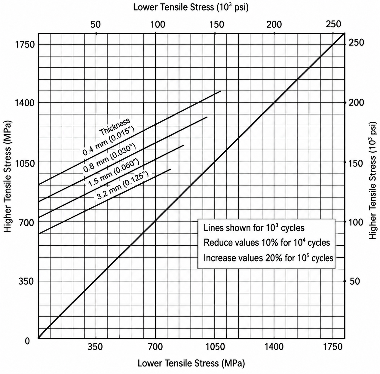 Modified Goodman Diagram — Fatigue Strength
New washers are pre-stressed once, after heat treatment, by compressing them beyond their intended working range (typically to about 2× the load at 75% of h). This deliberately yields the material right at cross-section point I (the compressive top-I.D. corner), which leaves a layer of beneficial residual compressive stress on the underside of the washer once the load is released. That residual stress partially cancels the tensile stress the washer sees later in service. This is why a preset washer tolerates a higher working stress than an unset one for the same fatigue life, the same principle as presetting a coil spring (card 06 in the compression-spring guide) or shot peening, above.
Preset too little and the benefit is marginal; the practical minimum preset deflection is about 0.15h to 0.20h (more at higher working stress). The preset compression itself is brief, so it only addresses the discrete overstress/yield mechanism. It does nothing to prevent the separate, time-and-temperature-driven relaxation and creep mechanisms covered in card 10. A preset washer can still lose preload slowly in a hot, long-dwell application; presetting and relaxation resistance are independent design decisions.
These three charts are the only fatigue-life data Bauer's catalog actually publishes for disc springs. There's no closed-form S-N equation behind them, just a read-off chart per DIN 2093 thickness group (card 07). Each plots the upper working stress σo against the lower working stress σu (both at whichever of ST1/ST2 governs), with three lines of constant life: 100,000 / 500,000 / 2,000,000 cycles. This calculator's "Estimated Life Cycle" field and the Material Fatigue Comparison table below the calculator read cycle life directly off these three digitized charts, interpolating between the life lines and scaling for material tensile strength relative to Bauer's baseline hardened spring steel. See that field's tooltip for the exact method and its limits.
Materials, Standards & Tolerances
Hardened carbon or alloy spring steel, typically finished to about HRC 47–50, gives the highest energy storage per unit volume and is the default choice whenever the environment allows it. When corrosion resistance or a non-magnetic part is required, austenitic stainless (301/302-type) is the common substitute, accepting a lower allowable stress in exchange. For elevated-temperature service or aggressive chemical exposure beyond what stainless can handle, nickel-based alloys such as Inconel X-750 retain their spring properties well past the temperature at which steel starts to relax. Beryllium copper and phosphor bronze are reserved for applications needing electrical conductivity or non-sparking behavior.
International standard DIN 2093 catalogs standard disc-spring diameters, thicknesses, and rated loads, which lets many designs use an off-the-shelf part instead of a custom one. SAE and ASTM references cover the spring-quality steel and stainless strip stock that finished discs are stamped from. Checking the catalog options before committing to a custom geometry can save both tooling cost and lead time.
Specify outside diameter with a minus-only tolerance and inside diameter with a plus-only tolerance — that combination guarantees clearance to the mating bore or pin never gets tighter than intended, no matter where in the tolerance band a given part lands.
Load tolerance should always be called out at a specific test height, not just at free height. As a starting point, washers with h/t below about 0.25 typically hold to around ±15% of rated load, while stiffer washers with h/t above 0.25 can usually be held to about ±10%. Nonferrous materials generally run closer to ±15% regardless of h/t. Tighter diameter or load tolerances are available from most manufacturers, but they add cost and should only be called out where the application genuinely needs them.
DIN 2093 sorts every disc spring into one of three groups by raw thickness t alone, and that group decides both how the washer is made and which fatigue-strength chart applies to it (card 06). Group 3 is the odd one out: it's ground or turned to a reduced contact-surface thickness t′ at the top and bottom edges (visible as the "reduced effective lever arm" in the lower cross-section of the figure), which is the K4 > 1 case already flagged in card 04. Groups 1 and 2 are geometrically identical to each other, made with a flat top and bottom edge all the way to the corner (K4 = 1, the case this calculator models) — they're only split apart because thin Group 1 stock is usually blanked or cold-formed while Group 2 is more often turned, and because Group 1's thinness earns it a separate fatigue-strength chart in card 06 despite sharing Group 2's geometry.
| Group | Disc thickness t [mm] | Contact surfaces, reduced thickness |
|---|---|---|
| 1 | < 1.25 | no |
| 2 | 1.25 to 6.0 | no |
| 3 | > 6.0 to 14.0 | yes |
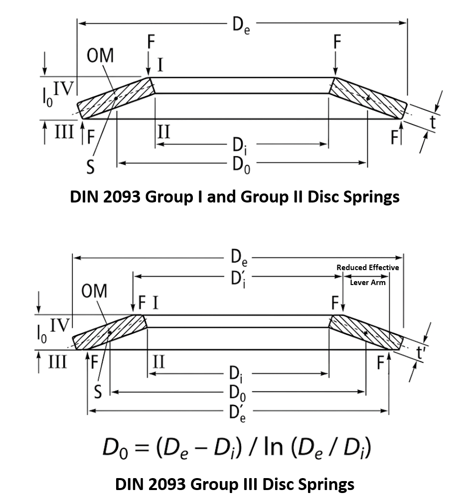 Groups 1/2 (Flat Edges) vs. Group 3 (Contact Surfaces)
Worked Design Example
A spring-loaded electrical contact assembly must maintain at least 220 N of clamping force across 0.50 mm of expected contact wear over its service life. Outside diameter is limited to 42 mm by the surrounding housing, and the part must resist corrosion, so an austenitic stainless washer is selected.
- Add margin to the minimum load target: design for roughly 10% above minimum, so 220 × 1.10 ≈ 242 N.
- Pick the diameter ratio R = OD/ID ≈ 2 — the proportion that stores the most energy per unit of material — giving an inside diameter of about 21 mm.
- Choose h/t = 1.41 from the curve family, since it holds a nearly constant load across the middle of its travel, matching the need to ride out 0.50 mm of wear without the force drifting much.
- Read the percent-load-at-deflection curve for h/t = 1.41: at roughly 50% of deflection to flat, load runs at about 88% of the load-at-flat value PF. That gives PF ≈ 242 / 0.88 ≈ 275 N.
- Cross-reference PF and the 42 mm outside diameter against the compressive-stress chart to estimate Sc, and confirm it sits comfortably below the static allowable for stainless without set removed (95% MTS).
- Solve the load equation for thickness t using PF, R, h/t, and the material's elastic modulus and Poisson's ratio.
- Lay out the working window: the initial preload deflection plus the full 0.50 mm of anticipated wear must both land inside the 15–85% band. If the wear pushes the upper end past 85%, shift the whole window down (for example to 40–85% instead of 50–100%) and repeat steps 4–6 with the new percentages.
- Once the static case closes, check ST1 and ST2 against the modified Goodman diagram if the contact is expected to cycle in service, and finalize dimensions and tolerances per the previous section.
Specification Checklist
- Material and hardness/temper
- Outside diameter (minus-only tolerance)
- Inside diameter (plus-only tolerance)
- Thickness
- Free (cone) height, h, and h/t ratio
- Flat bearing surface, if any, and its width
- Required load and load tolerance, and the test height it's measured at
- Allowable relaxation (%) over service life
- Required cycle life and reliability target, if cyclic
- Bore diameter the washer must clear, or pin diameter it must fit over
- Stack configuration: number in series, number in parallel, total count
- Maximum operating temperature
- Operating environment (corrosive, wash-down, vacuum, etc.)
Preload Retention Under Thermal Cycling
A bolted joint with no compliant element has almost no elastic reserve. The bolt itself only stretches a few thousandths of an inch before its clamp load is fully spent. Any shrinkage of the clamped stack, from thermal contraction, gasket creep, or settling, can zero out the clamp force entirely. A Belleville stack sized for a large working deflection, the whole point of the 15–85%-of-h range from card 03, turns that same length change into a small slice of a much bigger elastic range. A shrinking gap then costs only a modest fraction of the preload, not all of it. That is the entire reason disc springs get specified into thermally cycled clamps in the first place.
Within that picture, three separate effects move the preload as temperature swings. Only one of them is permanent.
The bolt and the clamped stack are almost never the same material, so they grow and shrink at different rates. Say the clamped stack's coefficient of thermal expansion (CTE) is higher than the bolt's. The classic case is an aluminum housing clamped by a steel bolt. Heating grows the housing faster than the bolt can follow, and the joint loses clamp deflection. Cooling does the reverse. Work this out for your own stack-up. Sum α·ΔT·L for every component in the load path, then compare the clamped-stack growth to the bolt's own growth over its grip length. Don't assume a direction; it flips depending on which material has the higher CTE.
Every equation in this guide carries E, the material's elastic modulus, as a direct multiplier on load. E falls as temperature rises for essentially every engineering metal. The drop is typically a few percent per hundred degrees for steels, more for some superalloys. So the same deflection produces measurably less force when hot:
This tracks temperature directly, and it fully recovers on cooling. It is not damage, just the material getting softer while hot. Get the real E(T) curve for your specific alloy from the material supplier. Don't assume a generic slope; it varies a lot between, say, carbon steel and a nickel superalloy.
This is the mechanism to actually design around. It's a different animal from both effects above. Held under sustained stress at elevated temperature, the material slowly creeps. The disc's residual elastic strain bleeds off over time, permanently shortening its effective free height. Unlike the modulus effect, relaxation does not reverse when the part cools back down. The lost preload is gone for good. It is also strongly time- and temperature-dependent, roughly exponential in absolute temperature. A clamp that looks fine after a short thermal excursion can still lose significant preload if it dwells at that same temperature for months or years.
"Taking a set" (card 06) is a related but distinct failure. It's a single, discrete overstress event, where a stress excursion crosses the material's yield-equivalent limit. Relaxation, by contrast, proceeds continuously, even at stresses the static allowable tables call safe. Heat drives it, not a single bad excursion. The two blend together at high enough temperature, though. Static allowables in this guide assume roughly room temperature. A design margined only against the room-temperature number can find its effective margin quietly eaten away, as sustained heat both relaxes the part and lowers the stress it can tolerate before actually setting.
- Bias the stack toward the h/t ≈ 1.41 constant-force plateau (card 02). Then, whatever deflection the CTE mismatch steals back, the load barely moves.
- Size in margin at both temperature extremes. Recompute with the hot-temperature E(T) and the cold-temperature E(T), not just the assembly-temperature value, and confirm clamp force stays above the application's minimum at both ends.
- For sustained high temperature, choose a material selected for relaxation resistance at that temperature (card 07). A nickel superalloy like Inconel X-750 or A286 will hold preload at temperatures where plain carbon or alloy steel would relax substantially within the first few hundred hours.
- Consider heat-setting the washers. Pre-relax them at or above the expected service temperature before installation, so the bulk of the relaxation loss happens in a controlled process, not silently over years in the field.
Bauer publishes measured relaxation curves rather than a formula — the six charts below are digitized straight from the catalog. Each plots relaxation (ΔF/F, the fractional loss of preload at constant length) against σOM for that washer's own DIN 2093 geometry series (A/B/C, card 02), at two hold times (48 hours and 1,000 hours) and two temperatures (20°C and 100°C). As expected, relaxation grows with higher stress, longer hold time, and higher temperature — the top curve on each chart (1,000 hours at 100°C) is the one to design against for a long-dwell hot application. The first three charts cover carbon spring steels to DIN EN 10132-4 (C67S, C75S, and similar); the second three cover chrome and chrome-vanadium alloyed stainless grades to DIN EN 10132-4 / DIN 17221 (X39CrMo17-1, X22CrMoV12-1, and similar) — use whichever set matches the material actually selected above.
Choosing Among Disc, Wave, Curved & Finger Washers
Belleville washers, wave washers, curved washers, finger spring washers, and stacked wave springs are all doing the same basic thing: a thin annular ring, formed out of flat, pushes back axially when compressed. What changes between them is how much force they give you, how much stroke they give you, and how much axial height that stroke costs. Picking the right one is mostly a matter of where your application sits on that trade-off, plus a couple of jobs (electrical contact, coil-spring-like travel) that only one shape really covers.
The Belleville washer, the subject of the rest of this guide, sits at one extreme: for a given radial envelope and axial height, it delivers the most force of the five, at the smallest deflection per washer. Stacking (card 05) trades some of that force back for more stroke, but a single disc is still the highest-force-density option here.
The curved washer sits at the other extreme. It's a single gentle curve rather than a true cone or wave, the simplest and cheapest of the five to produce, and by far the lowest-force option. It exists almost entirely to take up assembly slack: light bearing preload, anti-rattle, a small constant push against a race, nothing that needs real clamping force.
The wave washer (typically three waves around the circumference, single turn) is a step up from the curved washer: more force for the same material, at a moderate deflection, still a fraction of a Belleville's force density. It's the common drop-in for light-duty bearing preload where a Belleville would be overkill.
Nest wave washers crest-to-crest and you get a stacked wave spring: a compact substitute for a coil spring, with more total deflection and a more linear rate than any single washer in this family, in a much smaller radial envelope than a coil spring would need for the same force (though it does need more axial height than a single washer or a short Belleville stack).
The finger spring washer replaces the continuous wave or cone with cantilevered fingers. Force output is comparatively low, and the fingers are shaped to hold that force nearly constant across the working travel, which is exactly what steady electrical contact pressure needs through vibration and thermal cycling. If the joint also has to carry current or hold an EMI/RF shield path, this is usually the only one of the five actually built for that job.
These five don't have one shared, validated closed-form model the way the Belleville washer has DIN 2092, so this chart plots them as qualitative regions, not measured curves, positioned relative to each other by force density and available stroke for a roughly similar envelope. Treat it as a starting point for narrowing down a shape, then get real load-deflection data from the specific part or manufacturer.
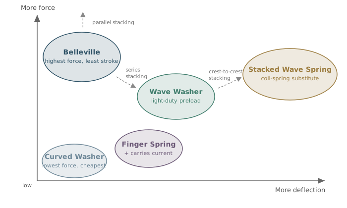 Relative Force vs. Relative Deflection, by Washer Type
Guiding & Centering Without a Separate Guide Element
Card 05's guide-pin/bore friction (contact (c) in the friction formulas there) is the one friction source that isn't reliably predictable from geometry — it dominates in long stacks and grows with taper angle, and a poorly guided stack can wear unevenly or walk sideways under load. The alternative is to build the centering into the washers or the stack hardware themselves, so the stack locates itself without sliding against a separate rod or bore at all. Bauer's catalog gives three ways to do this.
Each washer (or its mating end cap) is machined with an integral cylindrical shoulder that nests directly into the adjacent washer, locating the stack radially without any separate guide rod or sleeve. Because the shoulder itself requires machining, this is most practical on washers that are already fully machined on all faces — DIN 2093 Group 3, contact-surface springs (card 07) — where the extra step doesn't add a new manufacturing operation.
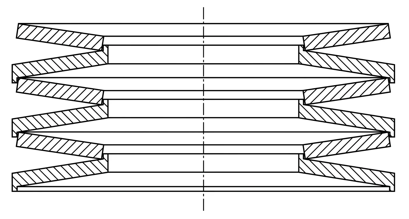 Centering Using a Cylindrical Shoulder
Separate rings, typically a shallow T-shaped cross-section, are inserted between alternating washers in the stack. Each ring locates against the O.D. or I.D. contact points of the washers on either side of it, holding the stack in radial alignment without requiring any machining on the washers themselves — a good option when the washers are off-the-shelf, unmachined parts.
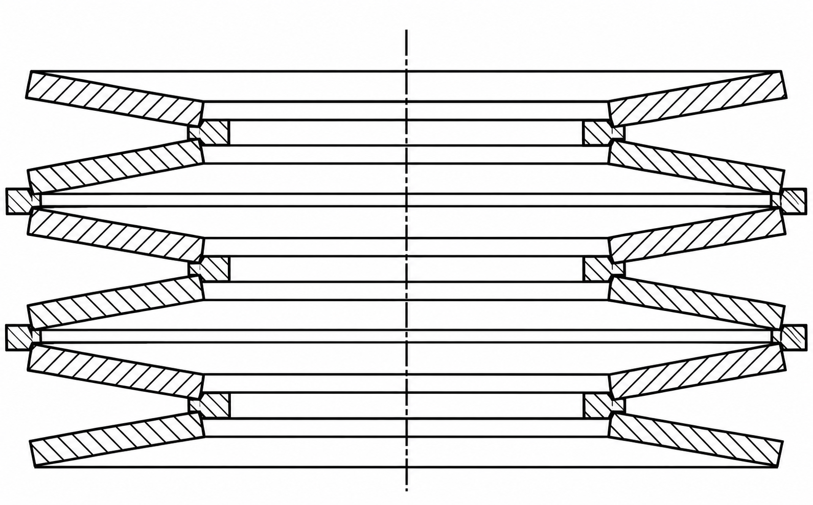 Intermediate Centering Rings
A shallow ring-shaped groove is machined near the O.D. (or I.D.) contact face of each washer. A set of small balls, or a segmented wire ring, sits in the groove between adjacent washers and provides the radial location — the balls or wire roll rather than slide, so this is the lowest-friction of the three self-centering methods, at the cost of the extra groove-machining and loose-parts handling.
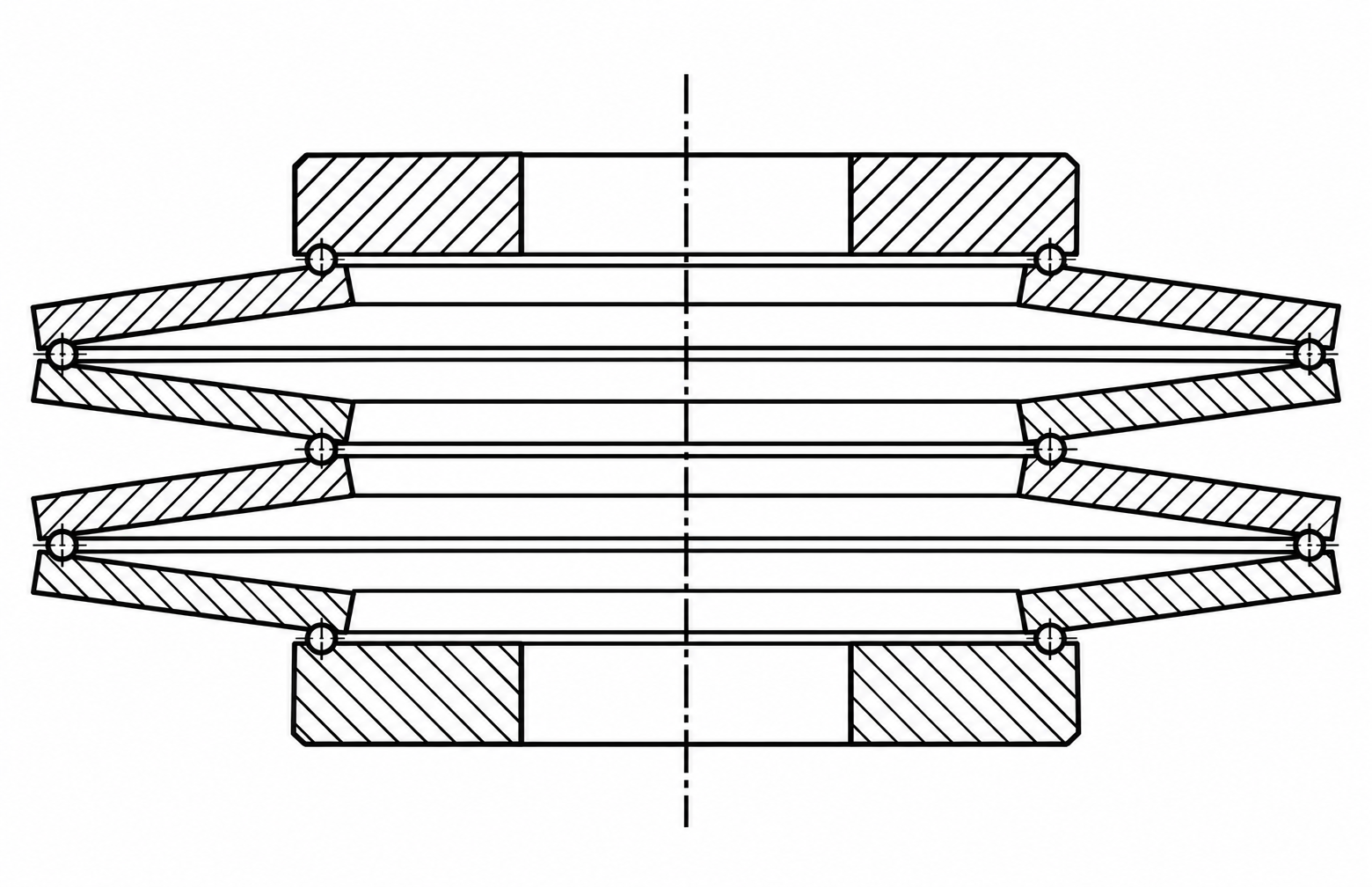 Ball / Wire-Ring Centering
When a stack is guided by a conventional rod or sleeve (card 05), which way the end washers face still matters, because it sets the surface pressure and relative sliding at the point where the stack actually contacts the moving compressing surface. Orient the washer's larger diameter — the O.D. — against the compressing surface rather than the I.D.: a larger contact circumference spreads the same force over more line-contact length, lowering local surface pressure and wear. For a stack with an uneven number of washers (so the two ends aren't mirror images of each other), orient whichever end washer sees the moving side of the joint so its O.D., not its I.D., faces that moving surface.
A part can also be centered between two opposed disc-spring stacks instead of resting on one — the same idea as a spring-centered valve or plunger. With both stacks pre-stressed against the part before it moves, the restoring force at any position is the difference between the two stacks' individual forces, and the combined rate is always higher than either stack alone would give — useful where a stiff, precisely centered return force matters more than maximum deflection. Without pre-stress, only the stack on the side the part moves toward resists the motion, and the restoring force is just that one stack's own load-deflection curve.
Stack Rules of Thumb & Dynamic Use
As a quick allowance, use about 2% to 3% per sliding surface. Use the friction equations above when you need more.
More parallel discs mean more rubbing. Heat from friction can cut fatigue life.
Common guidance is a few discs in parallel, often no more than four. Use a solid lubricant such as molybdenum disulfide.
Keep the stack height at or below three times the OD. Also keep it to about ten discs in series. Short stacks are more efficient.
Life depends on the deflection range. Keep dynamic deflection to about 75% to 80% of the maximum.
A higher final load raises stress and cuts life. A higher preload cuts the swing and adds life.
The h/t ratio shapes the curve and the fatigue life.