Anodize Tolerance Calculator for pre-anodize machining dimensions per MIL-A-8625 Type III hardcoat

Pre-Anodize Dimension Calculator

Calculate the dimensions a part must be machined to before anodizing, so that the finished part meets its drawing tolerances after anodizing. Covers flash hardcoat and full hardcoat per MIL-A-8625 Type III, Cl.1.

Note: Type II anodize per MIL-A-8625 adds no measurable dimensional change on machined features and requires no pre-anodize adjustment.

Anodize Reference: Types, Classes, Sealing & Color

Anodize is called out by Type (the process/acid), Class (undyed vs. dyed), and a seal. Coating thicknessi and color depend on all three plus the alloy. A typical drawing callout reads, e.g., “Anodize per MIL-A-8625 Type II, Class 2, black, dichromate seal.” The tables below summarize the common combinations and when to use each.

Thickness vs. buildup — key terms

  • Coating thicknessi — the full anodic oxide layer measured into one surface; this is what MIL-A-8625 and coating gauges report.
  • Buildup (per surface)i — only the outward-growing portion that changes the part dimension. For Type III this is about half the coating thickness (the 50/50 rule); for Type II it is roughly one-third. The calculators below use buildup, not coating thickness.
  • On a diameter both sides grow, so diametral growth = 2 × per-surface buildup.

Types — process, thickness, color, and when to use

Type Typical callout Process Typical coating thickness Typical buildup (per surface) Natural (undyed) color When to use
Type I MIL-A-8625 Type I, Cl.1/2 Chromic acid 0.00002–0.0001″
(0.5–2.5 µm)
Negligible
(~0.00001–0.00005″)
Gray to dark gray, iridescent Fatigue-critical parts; faying / lap joints & weldments where sulfuric could be trapped; paint & adhesive base. Minimal dimensional change.
Type IB MIL-A-8625 Type IB, Cl.1/2 Low-voltage chromic acid (22 V) 0.00002–0.0001″ Negligible
(~0.00001–0.00005″)
Gray Direct low-voltage alternative to Type I.
Type IC MIL-A-8625 Type IC, Cl.1/2 Non-chromic acid ~0.0001–0.0002″ Negligible
(~0.00005–0.0001″)
Light gray Chromate-free replacement for Type I / IB (hex-chrome elimination).
Type II MIL-A-8625 Type II, Cl.1/2 Sulfuric acid (conventional) 0.0001–0.001″
(Cl.1 min ~1.8 µm)
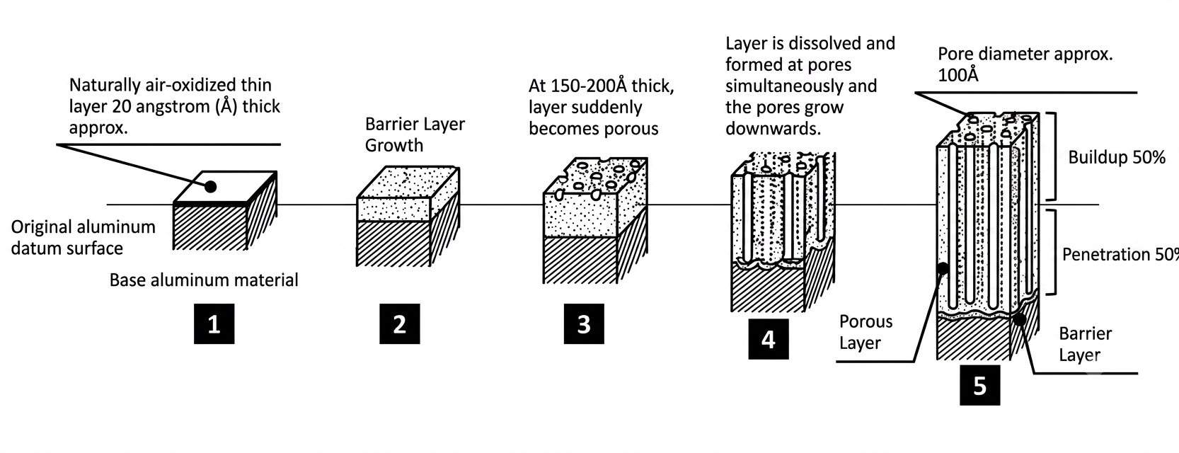
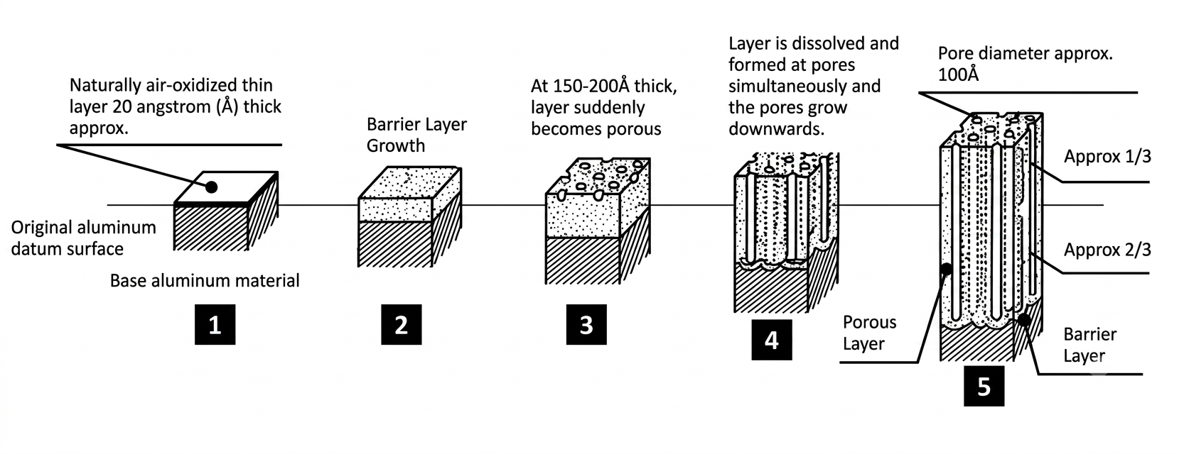
Negligible on machined features
(~0.00003–0.0003″, ~1/3 of coating)
Clear / silvery to light gray; readily accepts dye General corrosion protection, decorative dyeing, and paint base. Negligible dimensional change on machined features.
Type IIB MIL-A-8625 Type IIB, Cl.1/2 Thin sulfuric acid 0.00005–0.0004″
(1.5–10 µm)
Negligible
(~0.00002–0.00015″)
Light gray Thin, chromate-free alternative to Type I / IB where a sulfuric process is acceptable.
Type III
flash hardcoat
MIL-A-8625 Type III, Cl.1/2 Sulfuric acid (hard anodize), shorter cycle 0.0003–0.0005″ per surface 0.00015–0.00025″ Light gray to light bronze Hardcoat hardness & wear resistance where a thin coating and tight tolerances are needed. Modest dimensional buildup.
Type III
full hardcoat
MIL-A-8625 Type III, Cl.1/2 Sulfuric acid (hard anodize), full cycle 0.0005–0.0045″;
0.002″ (50 µm) typical
0.00025–0.00225″;
0.001″ typical
Gray-bronze to dark brown / black; darkens with thickness & alloy Maximum wear / abrasion resistance, electrical insulation, hydraulics, pistons, gears, bearings. Largest dimensional buildup — see calculators below.

Class 1 = not dyed (natural color shown above)
Class 2 = dyed.
Type II Class 2 takes the widest range of colors (black, red, blue, gold, green, etc.);
Type  III Class 2 is almost always dyed black. Chromic (Type I) coatings are too thin and opaque to dye reliably.

Sealing methods — color, corrosion resistance, and hazards

Seal Process Effect on color Corrosion resistance Hazmat When to use
Hot-water seal Hydration (boehmite) in ~190–212°F deionized water Minimal; may slightly cloud / soften dye shade Good Chrome-free Default seal where maximum corrosion resistance is not required; preferred where hex-chrome is prohibited.
Dichromate seal Hot sodium / potassium dichromate bath Adds a yellow / gold tint Excellent (chromate corrosion inhibitor) Contains hexavalent chromium (Cr VI) Salt-spray / corrosion-critical parts, especially Type I and Type II for aerospace & defense.
Nickel-acetate seal Mid-temperature nickel-salt bath Locks in dye; preserves color Good Nickel salts (sensitizer) Dyed Class 2 parts where color and fade resistance matter.
Duplex (dual) seal Dichromate seal followed by a hot-water seal Slight gold tint Best — chromate inhibitor plus full pore hydration Contains hexavalent chromium (Cr VI) Highest corrosion durability (aerospace / marine); combines the inhibitor of dichromate with the pore closure of hot-water sealing.

⚠ Hazardous materials note

Chromic acid anodize (Type I / IB) baths and dichromate seals (including the dichromate step of a duplex seal) contain hexavalent chromium (Cr VI), a known carcinogen regulated by OSHA, the EPA, REACH (SVHC / Annex XIV), and RoHS. This is the primary driver behind chromate-free alternatives such as Type IC, Type IIB, and non-chrome seals. All anodize processing also involves strong sulfuric or chromic acid electrolytes and a caustic (NaOH) pre-etch. Specifying and handling these finishes requires appropriate PPE, local exhaust ventilation, and licensed hazardous-waste treatment. Confirm environmental and regulatory requirements with your finishing vendor before releasing a callout.

How Anodize Affects Dimensions

The 50/50 rule — and why it is not universal

The most widely cited rule of thumb is that anodize is 50% penetration (into the base metal) and 50% build-up (on the surface). This is the basis for MIL-A-8625 guidance and the calculators on this page. Only the build-up portion changes the external dimension, so at a total coating of 0.002″ the surface grows by 0.001″ per side.

However, the 50/50 split is an approximation, and the actual ratio depends on anodize type and alloy:

  • Type III hardcoat — typically close to 50/50 in practice; Anoplate Corporation reports approximately 45% build-up / 55% penetration for Type III. The calculators use the 50/50 assumption because it is specified in MIL-A-8625 and is the basis for the Sanford Process tolerance guidelines.
  • Type II sulfuric anodize — approximately 1/3 build-up / 2/3 penetration. This is why Type II causes less dimensional growth per unit of coating thicknessi than hardcoat, and why many precision shops treat Type II as dimensionally negligible on machined features.
  • Type I chromic acid anodize — coating is so thin (typically <0.0001″ per surface) that dimensional change is negligible for virtually all machined features.
All other anodize types — ~50/50
Cross-section of anodize showing approximately 50 percent build-up and 50 percent penetration for non-sulfuric coatings
Type I, Type III hardcoat, and other non-Type II coatings: roughly 50% build-up / 50% penetration. This is the 50/50 rule the calculators on this page use.
Type II sulfuric anodize — ~1/3
Cross-section of anodize showing approximately one-third build-up and two-thirds penetration for Type II sulfuric anodize
Approximately 1/3 build-up / 2/3 penetration — less dimensional growth per unit of coating thicknessi than hardcoat.

Figure: Anodize build-up vs. penetration. Type III hardcoat is approximately 45% build-up / 55% penetration; Type II sulfuric is approximately 1/3 build-up / 2/3 penetration. Ratios vary with alloy and process parameters. Source: Anoplate Corporation, The Impact of Anodize on Dimensions.

⚠ Caution: The 1/3–2/3 rule that some vendors and references cite applies primarily to Type II sulfuric anodize. Applying it to Type III hardcoat underestimates the build-up and will produce parts that are out of tolerance. Always confirm the build-up ratio and tolerance range with your specific anodizer and process type.

Type II vs. Type III

  • Type II (sulfuric anodize) — decorative, corrosion protection. No dimensional adjustment required on machined features.
  • Type III — Flash hardcoat per MIL-A-8625 Type III, Cl.1: typical total buildup 0.0003–0.0005″ (per surface = half that).
  • Type III — Full hardcoat per MIL-A-8625 Type III, Cl.1: typical total buildup ±0.001″ (0.001″ per surface).

Natural and black hardcoat behave the same way dimensionally. Quantum Hard Color is typically thinner — 0.0013 ± 0.0003″ total buildup.

Thread features require larger adjustments

  • Major and minor diameters2× per-surface buildup (coating on two opposing surfaces).
  • Pitch diameter of 60° threads4× per-surface buildup (cos 30° geometry).
  • Root radius1× buildup (single curved surface).

Metal removal from pre-treatment

  • Etching (NaOH): removes 0.0001–0.0006″ per surface (1–4 min); up to 0.00075″ at 8 min.
  • Chemical brightening (acid polish): removes ~0.0001–0.00024″ per surface.

These calculators compute the pre-anodize dimension only. Add any etch/polish removal separately.

How to use these calculators

  1. Enter the nominal finished dimension and tolerances as they appear on the drawing after anodize.
  2. Enter the anodize buildup tolerances. Use the typical values shown as a starting point.
  3. Read the pre-anodize dimensions from the results table and use on the machining drawing.

OD / outer features: pre-anodize dimension is smaller (coating grows outward).

ID / inner features: pre-anodize dimension is larger (coating encroaches inward).

Calculator 1: Single Surface (Flat or Radius)

Use for one surface only — a flat face, outer radius, or inner radius. Typical flash hardcoat buildupi per surface: 0.00015–0.00025″. Typical full hardcoat: 0.0005–0.001″.

Calculator 1: Single Surface
Finished Dimension (after anodize) — from drawing
Nominal dimension (in):
Upper tolerance (in) +:
Lower tolerance (in) −:
Anodize Buildup per Surfacei
Anodize type / thickness:
Upper buildup tolerance (in):
Lower buildup tolerance (in):
After Anodize (drawing) Before Anodize
OD / Non-radius
Before Anodize
ID / Radius
Maximum
Minimum
Nominal ± tol

Calculator 2: Diameter (OD or ID)

Use for any cylindrical feature — shafts (OD), bores (ID), boss diameters, hole diameters. Coating builds up on both sides simultaneously. Typical flash hardcoat total diametral buildupi: 0.0003–0.0005″ (0.00015–0.00025″ per side). Typical full hardcoat: ±0.001″ total (0.0005–0.001″ per side).

Calculator 2
Diameter (OD or ID)
Finished Diameter (after anodize) — from drawing
Nominal diameter (in):
Upper tolerance (in) +:
Lower tolerance (in) −:
Anodize Buildup per Surface (half the total diametral buildup)i
Anodize type / thickness:
Upper buildup tolerance (in):
Lower buildup tolerance (in):
After Anodize (drawing) Before Anodize
OD (shaft / boss)
Before Anodize
ID* (bore / hole)
Maximum
Minimum
Nominal ± tol

* For an ID, the pre-anodize bore must be larger than the finished bore.

Calculator 3: Thread Major and Minor Diameter

For 60° threads (UN, UNF, metric): coating builds up on opposing flanks simultaneously. Effective diametral change is 2× per-surface buildup for major and minor diameters. Run each separately with the appropriate nominal diameter. Typical flash hardcoat: upper 0.00025″, lower 0.00015″. Typical full hardcoat: upper 0.001″, lower 0.0005″ per surface.

Calculator 3
Thread Major / Minor Diameter (×2 factor)
Thread Diameter (after anodize) — major OR minor
Nominal diameter (in):
Upper tolerance (in) +:
Lower tolerance (in) −:
Anodize Buildup per Surface (factor ×2 applied to diameter)i
Anodize type / thickness:
Upper buildup tolerance (in):
Lower buildup tolerance (in):
After Anodize (drawing) Before Anodize
External thread (OD)
Before Anodize
Internal thread (ID)*
Maximum
Minimum
Nominal ± tol

* For an internal thread (tapped hole), the pre-anodize diameter must be larger.

Calculator 4: Thread Pitch Diameter (60° Threads)

The pitch diameter of a 60° thread is affected by anodize on the thread flanks. Because the flanks are angled at 30° from the axis, the effective diametral change is 4× per-surface buildup (derived from 2 × 1/cos 30°). Typical flash hardcoat: upper 0.00025″, lower 0.00015″.

Calculator 4
Thread Pitch Diameter (×4 factor)
Pitch Diameter (after anodize) — from drawing
Nominal pitch diameter (in):
Upper tolerance (in) +:
Lower tolerance (in) −:
Anodize Buildup per Surface (factor ×4 applied to pitch dia)i
Anodize type / thickness:
Upper buildup tolerance (in):
Lower buildup tolerance (in):
After Anodize (drawing) Before Anodize
External thread (OD)
Before Anodize
Internal thread (ID)*
Maximum
Minimum
Nominal ± tol

* For an internal thread (tapped hole), the pre-anodize pitch diameter must be larger.

Calculator 5: Thread Root Radius (60° Threads)

The root radius is a single curved surface: buildup factor is 1× per-surface buildup. If adding anodize to an inner radius, the pre-anodize inner radius must be larger than the finished inner radius. Typical flash hardcoat: upper 0.00025″, lower 0.00015″ (1:1 factor).

Calculator 5
Thread Root Radius (×1 factor)
Root Radius (after anodize) — from drawing
Nominal root radius (in):
Upper tolerance (in) +:
Lower tolerance (in) −:
Anodize Buildup per Surface (factor ×1)i
Anodize type / thickness:
Upper buildup tolerance (in):
Lower buildup tolerance (in):
After Anodize (drawing) Before Anodize
Outer radius
Before Anodize
Inner radius*
Maximum
Minimum
Nominal ± tol

* Inner radius pre-anodize value is larger than the finished value.

References and Notices
  • MIL-A-8625F, Anodic Coatings for Aluminum and Aluminum Alloys — Type II (sulfuric, no dimensional change), Type III (hardcoat, 0.0003–0.002″ typical total buildup depending on class).
  • Sanford Process Corporation, Metal Tolerance Guidelines as it Relates to Hard Coat Classic and Quantum Hardcolor — source for etch and brightening metal-removal guidance. Calculator formulas verified against Sanford's ANODIZE_TOLERANCES_RevB.xlsx.
  • Anoplate Corporation, The Impact of Anodize on Dimensions — source for Type III 45%/55% build-up/penetration data and Type II 1/3–2/3 ratio discussion.
  • All dimensions in inches. These calculators are design screening tools. Final pre-anodize dimensions should be confirmed with your anodizing vendor before releasing machining drawings.

Cite This Work