Why Wire Gauge Matters

Every wire has resistance, and resistance costs voltage. In a 12 V system a wire that is too thin acts like a small resistor in series with your load. This means that some of the supply voltage is "spent" heating the wire instead of running the device. This can cause dimmer lights, sluggish motors, or a fire hazard.

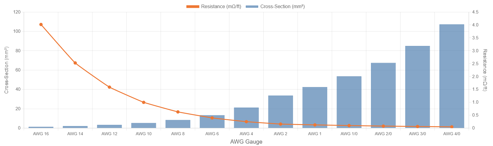
American Wire Gauge (AWG) is a standardized sizing system used throughout North America for copper conductors. Counter-intuitively, a lower AWG number means a thicker wire with lower resistance. AWG 4/0 (pronounced "four-ought") is the largest listed here at 107 mm², while AWG 16 is the smallest at 1.31 mm².

The 3 % Rule

The most widely cited rule for 12 V DC wiring (recommended by the ABYC (American Boat and Yacht Council) and common in automotive and RV practice) is to limit the total round-trip voltage drop to 3 % of nominal supply voltage, or roughly 0.36 V on a 12 V system. Beyond 3 % many devices begin to under-perform; at 10 % or more you risk equipment damage and serious heat buildup in the wire.

The physics behind the table below come directly from Ohm's Law. For a round-trip conductor of length L (one-way, in feet), cross-section A mm², and copper resistivity ρ = 0.01724 Ω·mm²/m:

Vdrop  =  I × 2 × ρ × (L × 0.3048) / A

Setting Vdrop ≤ 0.36 V and solving for the minimum cross-sectional area:

Amin  =  I × L / 34.27    (mm², with L in one-way feet)

The factor 34.27 comes from 0.36 / (2 × 0.01724 × 0.3048). Once Amin is known, the table below selects the smallest AWG gauge whose conductor area meets or exceeds that minimum.

Max Allowable Current vs. Wire Length (3% Rule)

Each line below shows the maximum current that keeps voltage drop at or below 0.36 V (3 % of 12 V) for a given AWG gauge. Pick the gauge whose line sits above your required current at your wire run length. Longer runs demand heavier wire.

Canvas Element Not Working, Please Check Browser Settings or Contact KasperCalc.

One-way wire length (ft). Current values assume copper conductor, 3% voltage drop limit (0.36 V on 12 V).
Toggle gauges by clicking the legend.

Minimum AWG Gauge Quick Reference Table

Find your one-way wire run length in the left column and your load current across the top. The cell shows the minimum AWG copper wire gauge required to stay within the 3 % voltage drop rule. When in doubt, go one size heavier.

Copper conductor, 12 V nominal, 3% drop limit. Length = one-way run in feet. Cells marked “> 4/0” exceed the range of this table and require a parallel run or bus bar.

12V Wire Gauge Calculator
Current Draw (A):
One-Way Wire Length (ft):
Minimum AWG Gauge:  
Min. cross-section (mm²):  
Conductor area of selected gauge:  
Round-trip resistance:  
Voltage drop at rated current:  
Worked Examples

Example 1: Marine Bilge Pump (20 ft run)

A 12 V bilge pump draws 8 A at full flow. The pump sits in the bilge and the breaker panel is 20 ft away (one-way). How heavy does the wire need to be?

Amin = 8 A × 20 ft / 34.27 = 4.67 mm²

AWG 10 has 5.26 mm² — that is the smallest gauge that meets the requirement. Round-trip resistance for 40 ft of AWG 10: 0.001 Ω/ft × 40 ft = 0.040 Ω. Voltage drop: 8 A × 0.040 Ω = 0.32 V (2.7% — within the 3% rule).

Example 2: Truck Winch (8 ft run)

A 12 V electric winch has a peak stall current of 400 A. The battery sits 8 ft from the winch motor. What gauge wire and how many parallel runs are needed?

Amin = 400 A × 8 ft / 34.27 = 93.4 mm²

AWG 4/0 provides 107.2 mm² and just meets this requirement as a single run. In practice, winch manufacturers typically specify two parallel 2/0 runs (2 × 67.4 = 134.8 mm² total) for mechanical reliability and reduced heat at the terminal lugs. Always follow the winch manufacturer's wiring recommendation.

Example 3: RV Rooftop Air Conditioner (35 ft run)

A 12 V compressor air conditioner draws 30 A. The inverter/battery bank is 35 ft from the unit. What gauge is needed?

Amin = 30 A × 35 ft / 34.27 = 30.6 mm²

AWG 2 provides 33.6 mm². Voltage drop: (2 × 0.0001563 Ω/ft × 35 ft) × 30 A = 0.328 V (2.7%). A single AWG 2 run is sufficient. Note that the cable must also be rated for the environment (see jacket materials below).

Copper vs. Aluminum Conductors

Aluminum is roughly 60 % as conductive as copper by cross-section, meaning an aluminum wire needs about 60 % more cross-sectional area to carry the same current with the same voltage drop. In practice, an aluminum wire must be two AWG steps larger than an equivalent copper wire (e.g., AWG 2 copper ≈ AWG 1/0 aluminum for the same ampacity).

Property Copper Aluminum
Resistivity (20 °C)0.0172 Ω·mm²/m0.0282 Ω·mm²/m
Relative conductivity100%~61%
Density8.96 g/cm³2.70 g/cm³
Weight for equal ampacityHeavier~50% lighter
Cost (general trend)HigherLower
Oxidation behaviorThin patina, conductiveHard oxide layer, insulating
Terminal compatibilityAll standard lugsRequires AL-rated lugs & anti-ox paste
Typical use in 12 V systemsPreferredLarge battery cable runs, weight-sensitive

Aluminum is common in large-format battery-to-inverter runs where weight matters, especially in RV and marine installations. For any aluminum connection, use AL/CU-rated compression lugs and apply an antioxidant compound. Aluminum should never be used for small-gauge wiring or where connections may be disturbed frequently; the oxide layer that forms on exposed aluminum is resistive and can cause high-resistance joints that arc and overheat.

Wire Jacket (Insulation) Materials

The insulation jacket protects the conductor from abrasion, moisture, and heat. Choosing the right jacket is just as important as choosing the right gauge. The wrong insulation can degrade, crack, and create a short circuit even when the conductor is properly sized.

Type Common Name Max Temp. Oil / Fuel Resistance Flexibility Typical Use
GPT General Purpose Thermoplastic (PVC) 60 °C (140 °F) Poor Good Interior auto wiring, body harness
TXL Thin-wall Cross-linked PVC 125 °C (257 °F) Moderate Excellent Engine bay, underhood wiring
GXL Cross-linked PVC, standard wall 125 °C (257 °F) Moderate Very Good General automotive, slightly harsher environments than GPT
SXL Cross-linked PVC, heavy wall 125 °C (257 °F) Good Good Marine engine rooms, areas with abrasion risk
SGX / SGT Starter / Battery Cable 90 °C (194 °F) Good Very Good Battery cables, starter leads, high-current runs
XLPE Cross-linked Polyethylene 90–105 °C Very Good Good Marine (ABYC compliant), solar PV wire
Neoprene Polychloroprene sheath 90 °C (194 °F) Excellent Excellent Portable cables, marine bilge, outdoor exposed runs
Silicone Silicone rubber 200 °C (392 °F) Moderate Excellent Near exhaust manifolds, heater elements, high-temp engine wiring
PTFE Teflon 260 °C (500 °F) Excellent Low Aerospace, turbocharger wiring, extreme-temperature applications
Wire Gauge Selection Procedure

Use the following six steps to size any 12 V DC wire run from first principles. The calculator above automates steps 1–4.

  1. Determine the total load current. Sum the nameplate current of every device on the circuit. Add a 25 % safety margin for motor starting surges or future load growth.
  2. Measure the one-way wire run length. Route the measurement along the actual cable path (around corners, through bulkheads), not point-to-point. Include both the positive lead to the load and the return/ground lead — they are both part of the circuit. The formula uses one-way length because the factor of 2 (round trip) is already included.
  3. Calculate the minimum conductor area. Amin = I × L / 34.27 mm² (copper, 3% drop limit on 12 V).
  4. Select the next larger standard AWG size. If the calculation yields 4.0 mm², choose AWG 10 (5.26 mm²), not AWG 12 (3.31 mm²).
  5. Verify the ampacity rating of the wire. Conductor area determines voltage drop, but the insulation type sets the continuous current limit. Confirm the chosen wire's ampacity (from manufacturer data or NEC/ABYC tables) equals or exceeds your load current. Derate by ~20 % if the wire runs in a bundle of four or more conductors; derate further for ambient temperatures above 30 °C.
  6. Size the fuse or circuit breaker. Fuse the wire, not the load. The fuse rating should be at or just below the wire's ampacity. Place the fuse as close to the power source as practical (within 18 inches of the battery terminal for primary circuits, per ABYC E-11).
AWG Reference: Cross-Section & Resistance

The bars show conductor cross-section area (left axis). The orange line shows DC resistance per foot (right axis). Heavier gauges have dramatically lower resistance. Going from AWG 10 to AWG 4 halves the resistance per foot.

Canvas Element Not Working, Please Check Browser Settings or Contact KasperCalc.

Resistance values are for copper conductor at 20 °C. Toggle datasets by clicking the legend.

AWG Copper Wire Properties Reference Table
AWG Area (mm²) Diameter (mm) Resistance (mΩ/ft) Typical Max Current*
161.311.294.01613 A
142.081.632.52517 A
123.312.051.58823 A
105.262.590.99933 A
88.373.260.62846 A
613.34.110.39560 A
421.25.190.24980 A
233.66.540.156100 A
142.47.350.124115 A
1/053.58.250.0982135 A
2/067.49.270.0779160 A
3/085.010.400.0618190 A
4/0107.211.680.0490230 A

*Typical maximum continuous current for single conductor in free air, 60 °C rated insulation. Derate for bundled wires, conduit, or elevated ambient temperature. Values are approximate; consult NEC Table 310.16 or ABYC E-11 for code-compliant design.

Additional Design Notes

Fusing

Every unfused conductor is a potential fire. The fuse protects the wire, not the appliance. Size the fuse to the wire's ampacity rating, and place it as close to the positive battery terminal as possible. A fuse should be within 18 inches for primary circuits per ABYC E-11. Use a blade fuse (ATO/ATC) for circuits up to 40 A, a MIDI or ANL fuse for battery and inverter cables above that.

Temperature Derating

Wire ampacity is rated at a standard ambient temperature, typically 30 °C (86 °F). In an engine bay or an enclosed box in summer sun, temperatures can exceed 60–80 °C. At 60 °C ambient, derate wire ampacity by roughly 20 %. Choose a wire rated for the maximum temperature it will actually see. Use TXL or XLPE for engine bays and silicone near exhaust manifolds.

Bundled Wires

When multiple current-carrying conductors run together in a loom, conduit, or tight bundle, each wire's heat has less path to dissipate. Apply a bundling derating factor: 0.80 for 4–6 conductors, 0.70 for 7–24, and 0.50 for 25 or more. In practice, for a bundle of 6 wires each rated 20 A, treat each as if limited to 20 A × 0.80 = 16 A.

Stranded vs. Solid Wire

For any mobile application (vehicles, boats, RVs) always use stranded copper wire. Solid wire work-hardens and fractures under repeated vibration. Marine-grade tinned-copper stranded wire resists corrosion further; the tin coating prevents the green verdigris that forms on bare copper strands in humid bilge environments.

Cite This Work