Orifice, Nozzle & Diffuser Flow Calculator — Compressible and Incompressible Flow Through Restrictions and Area Changes
Fluid data comes from live CoolProp lookups (gases & common liquids) or this site's own digitized density data (MIL-spec/aviation liquids — see Multi-Fluid Property Charts). Not currently available — gases: . Liquids: . Pick "Other" at the bottom of either list to enter properties by hand instead.
*Orifice mode uses the standard thin-plate, square-edged equation with real choked-flow handling for gases (the reference Valcor "Fluid Flow Through a Single Orifice" tool does not model choking). Nozzle and diffuser/cone modes use 1-D isentropic gas dynamics for gases and continuity + Bernoulli for liquids. Not a substitute for a full ISO 5167 / ASME MFC-3M metering design.*
Also See:
Fluid Velocity in Pipe CalculatorAlso See:
Density Dependent Flow Rate CalculatorAlso See:
Gas Mass Flow Rate CalculatorAlso See:
Thermo Land (Fluid Property Lookup)Orifice Flow Equation
For an incompressible liquid, flow through a thin-plate orifice follows from continuity and Bernoulli's equation between the upstream tap and the vena contracta:
Q = volumetric flow rate through the pipe/orifice
Cd = discharge coefficient — empirical, accounts for the vena contracta and real-fluid losses. Typically 0.60–0.62 for a sharp-edged concentric orifice at fully turbulent Reynolds numbers; adjust if a calibrated or standard-derived value (e.g. ISO 5167 / ASME MFC-3M) is known.
E = velocity of approach factor — corrects for the upstream pipe velocity not being negligible compared to the throat velocity
A2 = orifice bore area = (π/4)·d²
ΔP = differential pressure across the taps
ρ = fluid density
β = beta ratio = d/D
D = pipe ID
d = bore diameter
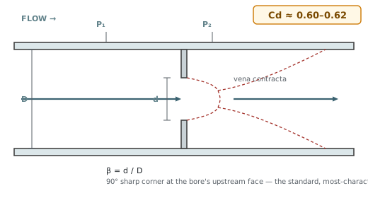
Orifice Opening Types
The bore's upstream edge profile (or, for the eccentric case, its position) changes how sharply the flow separates, which is exactly what the discharge coefficient is correcting for. This calculator's 0.60–0.62 default assumes the sharp-edged concentric case — the most common and best-characterized geometry; the other three are shown here for reference.
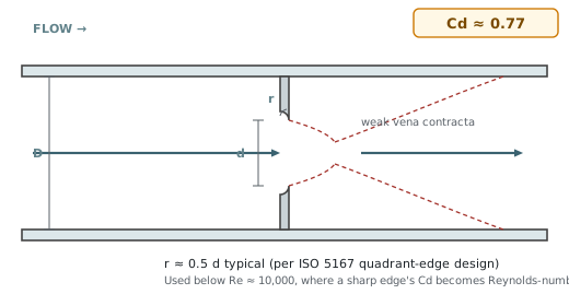
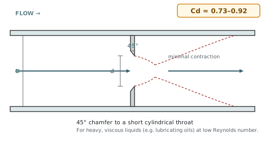
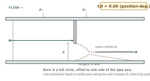
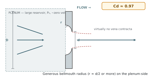
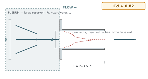
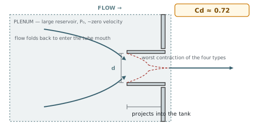
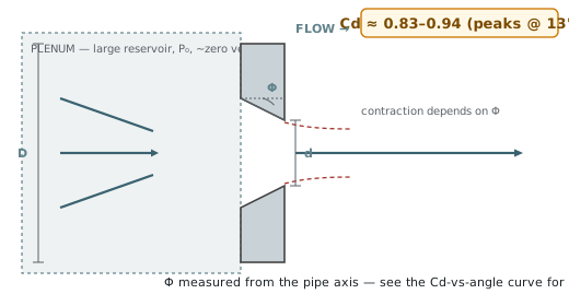
A related but different problem: a large reservoir (plenum) emptying through a hole or fitting in its wall, rather than a plate inline in a flowing pipe — the classic case for tank venting, blowdown, or relief sizing. This calculator's Orifice mode models the in-line plate case above, not these; they're shown here for reference since the same vena-contracta logic and discharge-coefficient concept applies.
Compressible (Choked) Flow — Gas Through a Restriction
For a gas, the liquid formula above is replaced with the isentropic flow equation for a converging passage, which is what makes choked flow show up correctly (the reference Valcor tool this calculator is modeled after does not do this — it uses the incompressible formula for gases too, which quietly over-predicts flow once the pressure ratio gets low). The downstream-to-upstream pressure ratio decides which branch applies:
Why Upstream Pressure Is What Matters (Not Just ΔP)
For a liquid, only the pressure difference ΔP = P₁ − P₂ matters — raising P₁ by 10 psi or dropping P₂ by 10 psi are physically identical, since density is constant either way. For a gas, especially once it's choked, that stops being true, and it's worth understanding exactly why — it's a genuinely different piece of physics, not a rounding error.
Density is ρ = P/(RT) — it depends on the absolute pressure level, not the drop across the restriction. Raise P₁ from 50 to 100 psia and also raise P₂ to keep ΔP the same, and the gas arriving at the orifice is now roughly twice as dense: the same ΔP pushes twice the mass through, because there's simply twice as much mass packed into every cubic foot approaching the hole. For a compressible fluid, ΔP never tells the whole story by itself the way it does for a liquid.
This is the sharper point, and it's a statement about causality, not just an approximation. Pressure changes propagate through a fluid as sound waves, at the local speed of sound, relative to the fluid. Once the throat is choked, the gas sitting right at the throat is already moving at exactly Mach 1 — the speed of sound. A pressure disturbance created downstream, by lowering P₂ still further, tries to propagate upstream through the throat to "announce" the change — but it's swimming upstream into a flow already moving at its own top speed. It never wins that race. It never reaches the throat. The throat genuinely cannot "hear" what's happening downstream of it anymore.
So raising P₁ always does something, whether choked or not (more ΔP and more density feeding the restriction), while lowering P₂ only does something until the throat goes sonic, at which point it does precisely nothing. Practically: if a choked vent, relief device, or pneumatic line is already choked, opening a bigger downstream path or pulling harder on the far side accomplishes nothing — the only lever left is upstream supply pressure.
Orifice Discharge Charts — Water & Air vs. Upstream Pressure
Four charts, same 8 sharp-edged orifice sizes discharging to atmosphere (50–200 psig upstream, 5 psi steps), computed analytically from the exact same equations as the calculator above — not digitized from a photo, and not a separate model. Air is choked at every single point on every air chart here (the critical pressure ratio for air is ≈0.528; P₂/P₁ never rises above ≈0.23 across this whole range), so the two air charts are a direct, literal demonstration of card 04's point: air mass flow (and SCFM, which tracks it) keeps climbing in a straight line with absolute upstream pressure, exactly as choked-flow theory predicts, with zero contribution from the fact that P₂ is fixed at atmospheric throughout.
Assumptions: Cd = 0.61, E = 1 (discharging from a large line/tank — the "Tank/plenum" fitting preset above), P₂ = 14.696 psia (atmosphere), water at ~68°F, air at 70°F with k = 1.4 / R = 287 J/(kg·K), SCFM referenced to 14.696 psia / 60°F. Hover any curve for the exact value at each 5 psi increment.
Converging & Converging-Diverging Nozzles
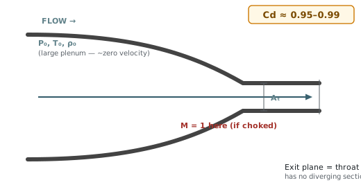
A Converging Nozzle uses the exact same choked-flow physics as the gas orifice above (it is the same throat mass-flow equation), just with a smooth contoured throat instead of a sharp-edged bore — so its discharge coefficient is much closer to 1 (typically 0.95–0.99) since there's no vena contracta to correct for.
A Converging-Diverging (de Laval) Nozzle is always choked at the throat (Mach 1) by definition when it's producing supersonic flow, so the mass flow rate depends only on the throat area — the exit area sets the Mach number, not the flow rate.
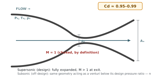
Every area ratio > 1 has two Mach roots — a subsonic one and a supersonic one. This calculator solves both: the supersonic root is the nozzle's fully-expanded design case, and the subsonic root is the same physical nozzle running well below its design pressure ratio (behaving like a simple venturi, never reaching Mach 1 at the throat). A real nozzle's behavior in between those two conditions (with a shock somewhere in the diverging section) is genuinely more complex and isn't modeled by either branch.
Diffuser / Cone — General Area-Change Physics
This mode answers the general "given the state at one end of a duct, what's the state at the other end" question for a smooth area change.
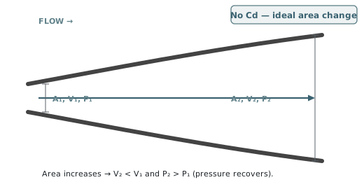
A converging cone is the opposite case: area decreases, flow accelerates, and static pressure drops.
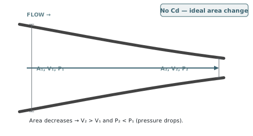
Gas (compressible, subsonic) — the stagnation state (P₀, T₀) is conserved along the duct; State 1 fixes an equivalent sonic throat area A*, then State 2's Mach number comes from A₂/A* on the isentropic area-Mach relation above (same solver as the C-D nozzle, subsonic root), and P₂/T₂ follow from the isentropic stagnation ratios.
Notes & Limitations
Fluid properties come from live lookups — real CoolProp equation-of-state data for gases and most liquids (via Thermo Land's data feed), or this site's own digitized density-vs-temperature curves for the MIL-spec/aviation liquids CoolProp doesn't carry (via Multi-Fluid Property Charts). Gas density and gamma (k) are the real fluid's values at the entered temperature and pressure, not an ideal-gas assumption — noticeably more accurate near the critical point or at high pressure than a constant-k model. See the calculator's own "gaps" note for which fluids aren't covered by either source.
All four modes are 1-D, steady, adiabatic, and (for gas) isentropic idealizations — friction losses, real nozzle boundary layers, and shock structures inside a C-D nozzle's diverging section aren't modeled. See the Gas Flow Safety Calculator for a complementary, safety-margin-focused take on compressible/choked gas flow.