INCH-POUND
MIL-W-5088L
10 May 1991
SUPERSEDING
MIL-W-5088K
24 December 1984
MILITARY SPECIFICATION
WIRING, AEROSPACE VEHICLE
This specification is approved for use by all Departments and Agencies of the Department of Defense.
1. SCOPE
1.1 Scope. This specification covers all aspects from the selection through installation of wiring and wiring devices used in aerospace vehicles. Aerospace vehicles include airplanes, helicopters, lighter-than-air vehicles, and missiles.
1.1.1 Application. This specification establishes design requirements guidance for wiring of aerospace vehicles. Although many of the requirements are written as mandatory and shall be considered as such, there is also considerable material which is intended to denote optional, preferential or guidance type requirements. In interpreting the material contained herein, it is intended that the philosophy of the entire document be considered for the wiring of each new type of vehicle. This philosophy is safety of the personnel, safety of the vehicle, satisfactory performance and reliability of the vehicle and ease of maintenance, and service life all at the least cost to the Government. The intent of this document will be fulfilled by tailoring the requirements in each new type or class of aerospace vehicle, to the proper application.
2. APPLICABLE DOCUMENTS
2.1 Government documents.
2.1.1 Specifications, standards and handbooks. Unless otherwise specified, the following specifications, standards and handbooks of the issue listed in that issue of the Department of Defense Index of Specifications and Standards (DODISS) specified in the solicitation form a part of this specification to the extent specified herein.
DISTRIBUTION STATEMENT A. Approved for public release; distribution is unlimited.
SPECIFICATIONS
MILITARY
| MIL-I-631 | Insulation, Electrical, Synthetic-Resin Composition, Nonrigid |
| MIL-I-3190 | Insulation Sleeving, Electrical, Flexible, Coated, General Specification for |
| MIL-C-3607 | Connector, Coaxial, Radio Frequency, Series Pulse, General Specification for |
| MIL-C-3643 * | Connectors, Coaxial, Radio Frequency, Series HN Associated Fittings, General Specification for |
| MIL-C-3650 | Connectors, Coaxial, Radio Frequency, Series LC |
| MIL-C-3655 | Connector, Plug and Receptacle, Electrical (Coaxial, Series Twin), and Associated Fittings, General Specification for |
| MIL-B-5087 | Bonding, Electrical, and Lighting Protection, for Aerospace Systems |
| MIL-E-6051 | Electromagnetic Compatibility Requirements, Systems |
| MIL-C-6136 | Conduit, Electrical, Flexible, Shielded, Aluminum Alloy for Aircraft Installations |
| MIL-E-7080 | Electric Equipment, Aircraft, Selection and Installation of |
| MIL-T-7099 | Terminal, Lug and Splice, Crimp Style Aluminum, for Aluminum Aircraft Wire |
| MIL-F-7179 | Finishes, Coatings, and Sealants for the Protection of Aerospace Weapons Systems, General Specification for |
| MIL-I-7444 | Insulation Sleeving, Electrical, Flexible |
| MIL-C-7762 | Compass, Installation of |
| MIL-B-7883 | Brazing of Steels, Copper, Copper Alloys, Nickel Alloys, Aluminum and Aluminum Alloys |
| MIL-T-7928 | Terminals, Lug and Splice, Crimp Style, Copper |
| MIL-S-8516 | Sealing Compound, Polysulfide Rubber, Electric Connectors and Electric Systems, Chemically Cured |
SPECIFICATIONS (continued)
MILITARY (continued)
| MIL-I-8700 | Installation and Test of Electronic Equipment in Aircraft, General Specification for |
| MIL-C-22520 | Crimping Tools, Terminal, Hand or Power Actuated, Wire Termination and Tool Kits, General Specification for |
| MIL-W-22759 | Wire, Electric, Fluoropolymer-Insulated, Copper or Copper Alloy |
| MIL-I-23053 | Insulation Sleeving, Electrical, Heat Shrinkable, General Specification for |
| MIL-S-23190 | Straps, Clamps and Mounting Hardware, Plastic and Metal for Cable Harness Tying and Support |
| MIL-S-23586 | Sealing Compound, Electrical, Silicone Rubber, Accelerator Required |
| MIL-I-23594 | Insulation Tape, Electrical, High Temperature, Polytetrafluoroethylene, Pressure-sensitive |
| MIL-M-24041 | Molding and Potting Compound, Chemically Cured Polyurethane |
| MIL-C-25516 | Connectors, Electrical, Miniature, Coaxial, Environment-resistant Type, General Specification for |
| MIL-C-26637 | Connector, Coaxial, Radio Frequency, Series LT, General Specification for |
| MIL-C-39012 | Connectors, Coaxial, Radio Frequency, General Specification for |
| MIL-C-39029 | Contacts, Electrical Connector, General Specification for |
| MIL-T-43435 | Tape, Lacing and Tying |
| MIL-C-49142 * | Connector, Plug and Receptacle, Electrical, Triaxial, Radio Frequency, General Specification for |
| MIL-A-55339 * | Adapter, Connector, Coaxial, Radio Frequency, (Between Series and Within Series), General Specification for |
SPECIFICATIONS (continued)
MILITARY (continued)
| MIL-M-81260 | Manual, Technical, Aircraft/System/Equipment Maintenance |
| MIL-W-81381 | Wire, Electric, Polyimide-insulated, Copper and Copper Alloy |
| MIL-T-81490 | Transmission Lines, Transverse Electromagnetic Mode |
| MIL-T-81714 | Terminal Junction System (TJS), Environment-resistant, General Specification for |
| MIL-T-81714/11 | Terminal Junction System (TJS), Terminal Junction Blocks, Sectional, Wire In-Line Junctions, Single, Series I |
| MIL-T-81714/12 | Terminal Junction System (TJS), Terminal Junction Blocks, Sectional, Wire In-Line Junctions, Double, Series I |
| MIL-S-81824 | Splice, Electric, Permanent, Crimp Style, Copper, Insulated, Environment-resistant |
| MIL-C-83517 * | Connector, Coaxial, Radio Frequency for Coaxial, Strip or Microstrip Transmission Line, General Specification for |
| MIL-S-83519 | Shield Termination, Solder Style, Insulated, Heat-shrinkable, Environment-resistant, General Specification for |
| MIL-C-85049 | Connector Accessories, Electrical, General Specification for |
| MIL-C-85485 | Cable, Electric, Filter Line, Radio Frequency Absorptive |
| MIL-S-85848 * | Sleeving, For Identification Marking, Heat Shrinkable, General Specification For |
STANDARDS
FEDERAL
| FED-STD-595 | Colors Used in Government Procurement |
MILITARY
| DOD-STD-100 | Engineering Drawing Practices |
| MIL-STD-454 | Standard General Requirements for Electronic Equipment |
STANDARDS (continued)
MILITARY (continued)
| MIL-STD-681 | Identification Coding and Application of Hookup and Lead Wire |
| MIL-STD-704 | Aircraft Electric Power Characteristics |
| DOD-STD-863 | Wiring Data and System Schematic Diagrams, Preparation of |
| MIL-STD-889 * | Dissimilar Metals |
| MIL-STD-970 * | Standards and Specifications, Order of Preference for the Selection of |
| MIL-STD-1353 | Electrical Connectors, Plug-in Sockets and Associated Hardware, Selection and Use of |
| MIL-STD-1388 | Logistic Support Analysis |
| MIL-STD-1553 | Digital Time Division Command/Response, Multiplex Data Bus |
| MS3373 | Strip, Mounting, Nut Insulating, for MS27212 Terminal Board |
| MS18029 | Cover Assembly, Electrical, for MS27212 Terminal Board Assembly |
| MS21266 | Grommet, Plastic, Edging |
| MS21919 | Clamp, Loop-Type, Cushioned, Support |
| MS25171 | Nipple, Electrical Terminal |
| MS25274 | Cap, Electrical (Wire End, Crimp Style, Type II, Class 1), for 105°C Total Conductor Temperature |
| MS25281 | Clamp, Loop-Plastic, Wire Support |
| MS25435 | Terminal, Lug, Crimp Style, Straight Type, for Aluminum Aircraft Wire, Class 1 |
| MS25436 | Terminal, Lug, Crimp Style, 90° Upright Type, for Aluminum Aircraft Wire, Class 1 |
| MS25437 | Terminal, Lug, Crimp Style, Left Angle Type, for Aluminum Aircraft Wire, Class 1 |
STANDARDS (continued)
MILITARY (continued)
| MS25438 | Terminal, Lug, Crimp Style, Right Angle Type, for Aluminum Aircraft Wire, Class 1 |
| MS25439 | Splice, Permanent, Crimp Style, 2 Way Type for Aluminum Aircraft Wire, Class 1 |
| MS25440 | Washer, for Use With Aircraft Aluminum Terminals |
| MS27212 | Terminal Board Assembly, Molded-In Stud, Electric |
| MS27488 | Plug, End Seal, Electrical Connector |
| MS33540 | Safety Wiring and Cotter Pinning, General Practices for |
| MS35489 | Grommet, Synthetic and Silicone Rubber, Hot Oil and Coolant Resistant |
| MS90376 | Cap, Dust, Plastic, Electric Connector |
| MS90387 | Tool, Hand, Adjustable, for Plastic Tiedown Straps |
| AND10380 | Coupling Installations, Standard Conduit, Electrical |
HANDBOOKS
MILITARY
| MIL-HDBK-216 | RF Transmission Lines and Fittings |
ADDITIONAL DOCUMENTS
Additional documents pertaining to the selection of wire and cables are listed in Appendix A.
*(Unless otherwise indicated, copies of federal and military specifications, standards and handbooks are available from the Standardization Documents Order Desk, Bldg. 4D, 700 Robbins Avenue, Philadelphia, PA 19111-5094.)
* 2.2 Non-Government publications. The following documents form a part of this document to the extent specified herein. Unless otherwise specified, the issues of the documents which are DOD adopted are those listed in the issue of the DODISS cited in the solicitation. Unless otherwise specified, the issues of the documents not listed in the DODISS are the issues of the documents cited in the solicitation (see 6.2).
AEROSPACE INDUSTRIES ASSOCIATION OF AMERICA, INC. (AIA)
| NAS 813 | Cap - Protective Electrical Connector |
| NAS 820 | Plug - Protective Electrical Connector |
(Application for copies should be addressed to the Aerospace Industries Association of America, Inc., 1250 Eye Street, N.W., Washington, DC 20005.)
AMERICAN NATIONAL STANDARDS INSTITUTE (ANSI)
| Y14.15 (1966) | Electrical and Electronics Diagrams |
| Y32.2 (1975) | Graphic Symbols for Electrical and Electronics Diagrams |
| Y32.16 (1975) | Reference Designations for Electrical and Electronic Parts and Equipment |
(Application for copies should be addressed to the American National Standards Institute, Inc., 1430 Broadway, New York, NY 10018-3308.)
(Industry association specifications and standards are generally available for reference from libraries. They are also distributed among technical groups and using Federal agencies.)
2.3 Order of precedence. In the event of a conflict between the text of this document and the references cited herein (except for related associated detail specifications, specification sheets, or military standards), the text of this document takes precedence. Nothing in this document, however, supersedes applicable laws and regulations unless a specific exemption has been obtained.
3. REQUIREMENTS
3.1 Terminology interpretation. The term "wiring" wherever used throughout this specification shall be interpreted in accordance with 6.3.5.
3.1.1 Deviations. Deviations from this specification desired by the contractor (substitution of equipment, material or installation) shall be specifically brought to the attention of the procuring activity by letter concurrent with or prior to forwarding the design data for approval. All requests for deviations shall include sufficient engineering information to substantiate the deviations.
3.2 Conflicting requirements. In case of discrepancies between this specification and the type or detail specification for a particular vehicle part, the type or detail specification shall prevail.
* 3.3 Selection of parts and materials. Parts and materials covered by documents listed herein are standard and shall be used whenever they are suitable for the purpose. Parts and materials shall be procured from QPL sources when they exist. Nonstandard parts and materials must be equivalent to or better than similar standard parts and materials. When this specification fails to provide an applicable specification or standard, the contractor shall use other established specifications or standards in the order of precedence set forth in MIL-STD-970. Parts and materials selected from other than those specified in this specification are not standard, and approval must be obtained prior to their use in aerospace vehicles. Each vendor source for a nonstandard part or material requires approval. When a nonstandard part is used where a suitable standard part exists, the contractor shall reference the standard part on the drawing, parts lists, or data package, and the installation shall provide for replacement with the standard part.
3.3.1 Requests for approval of nonstandard parts. The data to be submitted with the request for approval of nonstandard parts shall be in accordance with the terms of the contract.
3.3.2 Commercial utility parts. Commercial utility parts, such as screws, bolts, nuts, cotter pins, etc., may be used, provided they have suitable properties and are replaceable by standard parts without alteration.
3.3.3 Contractor's specifications. Wiring and wiring devices conforming to contractor's specifications may be used, provided each contractor's specification is approved by the procuring activity and provided no military specification exists. The contractor shall provide substantiating test data and, when required by the procuring activity, shall provide samples for test. The use of contractor's specifications shall not constitute waiver of Government inspections. Contractor's specifications shall follow the format for military specifications. When a detail or general military specification exists for the class of material required, the contractor's specification shall reference the existing military specification and set forth only the needed new requirements and deviations.
3.3.4 Commonality. An objective in the selection of parts shall be to maximize commonality and minimize the variety of wiring components and related servicing tools required in the construction, installation and maintenance of the electrical wiring system.
3.3.5 Government-furnished Aircraft Equipment (GFAE). Wiring and wiring devices furnished by the Government shall be installed without modification unless otherwise authorized or directed by the procuring activity.
3.3.6 Modification. The contractor shall not alter, rework or modify wiring or wiring devices built to and meeting Government specifications, unless authorized or directed by the procuring activity, and such modification shall be subject to Government inspection. Modified parts shall have the Government identifying part number removed and shall be identified by contractor part number.
3.4 Service life. The wiring and associated components used for the wiring installation shall be so selected and installed to promote ease of maintenance and high reliability over the entire expected service life of the vehicle. The reliability and maintainability goals for the wiring system will be determined in the Logistic Support Analysis as delineated in MIL-STD-1388 as will the expected service life. These goals shall be subject to procuring activity approval.
3.5 Smoke and fire hazards. Wiring and wiring devices shall be selected and installed in such a manner as to minimize the danger of smoke and fire hazards. Adequate protective means, both physical and electrical, shall be employed to provide reliability and safety commensurate with this requirement.
3.6 Materials. Materials used in the installation of wiring and equipment shall be suitable for the purpose and shall conform to such Government specifications as are specifically applicable under the contract.
3.6.1 Metals. Metals used in the installation of wiring shall be corrosion resistant or shall be suitably protected to resist corrosion and electrolytic action during normal service life. Finish and coating shall be in accordance with MIL-F-7179.
* 3.6.1.1 Dissimilar metals. Dissimilar metals used shall conform to the requirements of MIL-STD-889. This standard establishes requirements for the selection and protection of dissimilar metal combinations and other significant corrosion behavior factors.
3.6.2 Nonmetals. Nonmetals used, including plastics, fabrics and protective finishes, shall be moisture and flame resistant, shall not support fungus growth, shall not support combustion, and shall not be adversely affected by weathering, applicable fluids and propellants, temperature and ambient conditions encountered during operation of the vehicle. Materials that give off a minimum amount of noxious gases shall be selected. Nonmetals may be treated to conform to this requirement.
3.6.2.1 Insulating materials. Insulating materials shall have an arc resistance capability which will meet the circuit requirements.
3.6.3 Sealing materials. Only materials that are elastomeric and reversion resistant shall be used. Sealing materials required to seal wire junctions and terminations shall be selected from MIL-S-8516, MIL-S-23586, or other material specifically approved by the procuring activity. MIL-S-8516 is the preferred material. The following temperature limits apply (the upper limit includes ambient plus temperature rise):
| MIL-S-8516 | -51°C (-60°F) to 93°C (200°F) |
| MIL-S-23586 | -65°C (-85°F) to 232°C (450°F) |
3.6.3.1 Process. Sealing materials shall be applied in strict conformance with the manufacturer's instructions. Overage material shall not be used. The sealing material shall be held in place by suitable forms during the curing process.
3.7 Component selection and installation. Components and wiring devices shall be suitable for their application and selected and installed in accordance with the requirements of this specification. In addition, selection and installation considerations shall be made relative to vehicle operation and servicing environments to ensure that they are not subjected to conditions exceeding the limits specified in the applicable wiring component specifications.
3.7.1 Maintenance considerations. The maintainability of the wiring system shall be a prime consideration in the selection, design and installation of harnesses, cable assemblies and wiring system components. All wiring shall be accessible, repairable and replaceable at the maintenance level specified by the procuring activity. Other specific requirements concerning maintenance are specified in the appropriate paragraph on the subject.
3.8 Wiring selection. Wiring shall be of a type suitable for the application. Wire shall be selected so that the rated maximum conductor temperature is not exceeded for any combination of electrical loading, ambient temperature, and heating effects of bundles, conduit and other enclosures. Typical factors to be considered in the selection are voltage, current, ambient temperature, mechanical strength, abrasion, flexure and pressure altitude requirements, and extreme environments such as Severe Wind and Moisture Problem (SWAMP) areas or locations susceptible to significant fluid concentrations. The wire shall be selected in accordance with Appendix A of this specification. The wire selection shall take into account all requirements of this specification and the following design considerations.
3.8.1 Elevated temperature degradation. Degradation of tin and silver plated copper conductors will occur if they are exposed to continuous operation at elevated temperatures. These effects shall be taken into account in the selection and application of wiring.
3.8.1.1 Tin plated conductors. Tin-copper intermetallics will form resulting in an increase in conductor resistance. The increase is inverse to size, being up to 4 percent for the smallest gage.
3.8.1.2 Silver plated conductors. Degradation in the form of inter-strand bonding, silver migration, and oxidation of the copper strands will occur with continuous operation near rated temperature, resulting in loss of flexibility. Due to potential fire hazard, silver plated conductors shall not be used in areas where they are subject to contamination by ethylene glycol solutions. These conditions should be considered in the application of wiring using these conductors.
3.8.1.3 Solderability. Both tin plated and silver plated copper conductors will exhibit poor solderability after exposure to continuous elevated temperature. Compensating steps shall be included in maintenance procedures for retermination.
3.8.2 Aluminum wire. The use of aluminum wire requires procuring activity approval. Aluminum wire shall be restricted to size 8 and larger. Aluminum wire shall neither be directly attached to engine-mounted accessories nor installed in other areas of severe vibration. It shall not be installed where frequent connections and disconnections are required. All installations of aluminum wire shall be relatively permanent. Aluminum wire shall not be used where the length of run is less than 3 feet, nor in areas where corrosive fumes exist. Aluminum wire shall be terminated only by terminations specifically approved for this application (see 3.20.2).
* 3.8.3 Deleted.
* 3.8.4 Coaxial cables. Coaxial cables shall be suitable for the application and shall be selected in accordance with 30.1.5 of Appendix A. For applications above 400 MHz and in critical RF circuits, critical electrical characteristics such as attenuation, capacitance, structural return loss, environmental requirements, short leads and grounding shall be considered in design. MIL-HDBK-216 shall be used as a guide in their selection. Coaxial cable operating in the Transverse Electromagnetic Mode (TEM) and coaxial cable with tubular metal outer surfaces shall be identified by a violet colored marker (1 inch nominal width) at intervals not greater than 24 inches of length and within 6 inches of termination. Transmission lines in accordance with MIL-T-81490 need not be identified by colored markers if the color requirements of MIL-T-81490 have been met.
* 3.8.5 Harnesses. Harnesses shall be of either open or protected design. Open harnesses are preferred for maintenance considerations. Harnesses may be designed to meet mechanical or shielding requirements. The use of protected harnesses shall be avoided unless wiring design considerations dictate their use and is subject to the approval of the procuring activity. The design details of protected harnesses are also subject to the approval of the procuring activity.
3.8.6 Insulation compatibility with sealing and servicing. Wiring terminations in devices where the wiring must be sealed to provide an environment-resistant joint, shall have insulation compatible with the sealing feature of the device. Elastomer grommets are generally qualified to seal on wires having smooth extruded insulations. Only one wire per grommet hole is permitted. Sealing on tape wrapped, braided, striped, or other than smooth circular insulations shall be specifically tested for compatibility and shall be subject to procuring activity approval, unless compatibility has been demonstrated in the qualification of the terminating device. After installation in the vehicle, the integrity of the sealing features of all such devices shall be intact, and able to perform their function. A device shall be considered as sealed if the outermost sealing feature (web) is in full contact with the device when visually inspected. The wiring shall be installed so that transverse loads will not destroy the integrity of the sealing feature of the wire.
3.8.6.1 Wire diameter. The finished wire outside diameter shall be within the limits specified for the grommet specified in the appropriate component specification and shall not exceed the capability of contact servicing tools to insert and release contacts.
* 3.8.6.2 Potting seal on wire. The potting shall be bonded to the outermost surface of the wire or cable in such a way to ensure an environmental-resistant seal.
3.8.6.3 Insulation degradation. Wiring shall be handled, stripped and installed so as not to distort, roughen or damage the insulation on which sealing is to be effected. Methods of marking and identification shall be applied so as not to provide a track for moisture entry. The impression left on the insulation of shielded and twisted wires can also cause unacceptable degradation of the insulation in relation to the elastomer seal. Caution shall be used to avoid this condition.
3.8.7 Corona prevention. In the selection of wiring, considerations shall be given to the prevention of corona discharge. Useful information relating to corona prevention is contained in 6.6 and should be reviewed prior to the selection of all wiring.
* 3.8.8 Minimum wire size. This specification permits the use of size 22 wire as the minimum wire size for airplanes, helicopters and lighter-than-air vehicles, and prohibits size 24 and smaller gages (see 3.8.8.3 for missiles). This restriction in aerospace vehicle applications is due to maintenance difficulties.
* 3.8.8.1 Current carrying capacity. A guideline for the continuous current in each wire is shown in table I. Table I assumes an ambient temperature of 70°C, a harness or harness branch of 33 or more wires for sizes 26 through 10, and 9 wires for size 8 and larger, carrying 20 percent or less of rated harness or harness branch current and operating at an altitude of 60,000 feet. The use of this tabulation shall not eliminate other requirements for wire selection. Data from figures 3, 4 and 5 may be used for determining wire size for conditions other than those contained in table I. The use of table I and figures 3, 4 and 5 shall not eliminate other requirements for wire selection.
* 3.8.8.1.1 Wiring in harnesses. Table I current ratings for wires in harnesses are based upon 33 or more wires for sizes 26 through 10 and 9 wires for size 8 and larger at 60,000 feet altitude, and an ambient temperature of 70°C. The total current carried by the harness shall not be more than 20 percent of the numerical total obtained by adding the carrying capacities taken from table I (or calculated from figures 3, 4 and 5 for ambients, altitudes or harness loading factors differing from those assumed in table I), for the appropriate wire construction temperature rating for all the wires in the harness. For example, if a wire harness contains 33 size 20 wires rated at 200°C, the numerical total is 330 amperes, 20 percent of which is 66 amperes and the maximum allowable total current in the harness is 66 amperes and the maximum allowable current for any size 20 wire in the harness is 10 amperes. A cable in a harness shall be treated as a number of individual wires equal to the number of conductors in the cable, excluding shields.
In smaller harnesses, the allowable percentage of total current may be increased as the harness approaches the single wire configuration. The harness ratings contained in table I were derived from figures 3, 4 and 5. Single wires in free air ratings for copper wire were determined at ΔT (200°C - 70°C) (for aluminum wire derate the free air rating of copper wire by 20 percent) and derated for (a) operation at 60,000 feet altitude, (b) harnesses of 33 wires or more, and (c) carrying 20 percent or less of rated harness current. For conditions other than (a) through (c), refer to 6.7.
3.8.8.1.2 Wire terminations. The continuous current ratings of table I were derived only for wire application, and cannot be applied directly to associated wire termination devices (e.g., connector contacts, relays, circuit breakers, switches). The current ratings are limited by the design characteristics of the device. Care shall be taken to ensure that the continuous current value chosen for a particular system circuit shall not create hot spots within any circuit element which leads to premature failure. Acceptable temperature levels of circuit components shall be those defined by the particular circuit component specification.
* 3.8.8.2 Ambient temperature. The contractor shall ensure that the maximum ambient temperature that the wire bundles will be subjected to, plus the temperature rise due to the wire current loads, does not exceed the maximum conductor temperature rating found in Appendix A in tables A-I and A-II. Figures 3, 4 and 5 may be used to determine the appropriate current loads when the following conditions are known: maximum ambient temperature, maximum conductor temperature, maximum altitude and the number of wires in a bundle. See example in 6.7 for method of calculation.
* 3.8.8.3 Missile wiring application. For missiles only, use of size 24 high tensile strength copper alloy wire is permitted when bundled with other wires.
3.8.8.4 Voltage drop. For power distribution circuits, the total impedance of supply and return paths shall be such that the voltage at the load equipment terminals is within the limits of MIL-STD-704.
3.8.9 Maintainability. Wire selection shall be affected by considerations of the types and frequency of maintenance action.
3.8.10 Wiring selection for special applications. The general purpose wires listed in Appendix A do not perform equally in all applications. The detail characteristics of the specific wire types shall be considered for the following special applications.
* 3.8.10.1 Severe wind and moisture problems (SWAMP). Suitable wire types in accordance with MIL-W-22759 are preferred for severe wind and moisture problems (SWAMP) or both. Applications include wheel wells, near wing flaps, wing folds and pylons.
3.8.10.2 Frequency flexure. Suitable wire types selected from MIL-W-22759 are preferred for areas that require repeated bending and flexing of the wiring.
3.8.10.3 Electromagnetic Interference (EMI) and Electromagnetic Vulnerability (EMV) sensitive areas. MIL-C-85485 is preferred for use in EMI and EMV sensitive areas.
* 3.8.10.4 Thermocouple wiring. The following is required when using thermocouple wires (see 6.8):
- The use of thermocouple contacts is discouraged and should be used only if essential to meet system requirements, such as thermal gradient conditions. Crimp terminations are preferred.
- Transition from thermocouple wires to copper wires are permitted with the environmental sealed connectors specified in 3.14.1 or MIL-T-81714/12, type 2 in-line junction. When gold-plated crimping pairs are used, precautions should be taken to ensure that the connector external temperature ambient and internal hotspot temperature is such that both the wire to contact junctions for the thermocouple wires within the connector are at the same temperature.
- Splicing of thermocouple wire shall be avoided. If splicing is necessary (see 3.19) a MIL-T-81714/12, type 2 dual in-line junction (splice) or MIL-T-81714/11 single in-line junction (splice) or MIL-S-81824/1 splice shall be used.
- The connector, in-line junction, or splice shall provide an environmental seal on the thermocouple wire. The tensile characteristics of the contact/thermocouple combination shall be equal to or greater than the tensile characteristics of the thermocouple wire.
* 3.9 Wire and cable identification. Each wire and cable shall be marked with an identification code on the jacket or sleeving of the wire and cable. Hot stamp marking of wire and cable shall not be used unless other marking methods are not compatible with wire or cable insulation.
3.9.1 Assignment of identification code. The identification code for wiring shall be significant or nonsignificant in accordance with Appendix B or C, as specified by the procuring activity.
3.9.2 Deleted.
3.9.3 Marking.
3.9.3.1 The wire identification code shall be printed to read horizontally from left to right or vertically from top to bottom. See figures B-1 and B-2.
3.9.3.2 The characters shall be legible and permanent and the method of identification shall not impair the characteristics of the wiring.
* 3.9.3.3 Wiring shall be identified, throughout its length, at intervals not longer than 3 inches, as measured from the end of a mark to the beginning of the next mark.
* 3.9.3.3.1 When it is not possible to print directly upon a wire or cable, an identification marker shall be used. The marker shall be a MIL-S-85848 or MIL-I-23053 heat-shrinkable sleeve; a MIL-S-23190 (MS3368) identification strap, see 3.11.3.8) or a MIL-I-3190 glass braid. The marker shall not be used as an electrical insulating device. The markers shall be used as follows:
(NOTE: MIL-S-23190 (MS3368) identification strap shall not be used within cables, groups, harnesses or bundles.)
- Cables upon which identification cannot be printed shall be identified by printing the identification code (and individual wire color, where applicable) on a marker placed external to the outer covering at the terminating end or a common jacket shall be identified with printed markers at each end and at intervals not greater than 3 feet. Individual wires within a cable shall be identified within 3 inches from their termination.
- Wires on which identification cannot be marked shall be identified by printed markers at each end and at intervals not greater than 3 feet.
- Wires for which the identifications are reassigned after installation in the aircraft may be reidentified by markers at the termination of each wire segment. It is not necessary to reidentify such wires throughout their lengths.
3.9.3.3.2 Short wires and cables less than 6 inches in length need not be identified in the aircraft, but shall be completely identified on the drawing.
3.9.3.3.3 For developmental model aircraft, wiring identification may be provided at junction and termination points only.
* 3.9.3.3.4 For protected harnesses and shielded, jacketed multi-conductor cables and when using nonsignificant wire identification, color coding or its alphanumeric equivalent may be interchanged within the same harness. The alphanumeric equivalent of the color code shall be in accordance with MIL-STD-681. See paragraph 30.2.3.3 in Appendix C for an example of alphanumeric equivalent of color coding.
3.9.4 Connector identification. Connectors shall be identified to facilitate mating. All plugs shall have a nonmetallic band affixed to the wire group, cable or harness. This band shall bear the P and J number identification of both the plug and the mating receptacle and the equipment nomenclature. The band shall be within 6 inches of the plug. All receptacles shall be identified with a "J" number on both sides of the structure, adjacent to the receptacle. Receptacles, such as test and power, to which a mating plug is not attached, shall have, in addition, the function of the receptacle identified on the plug side of the structure.
* 3.9.5 Wire size color code system. When approved by the procuring activity, a wire size color code system as specified below may be used to facilitate control of the wire size. When a wire size color code is used, the wire insulation shall be identified with the appropriate color by one of the following methods. Only one method may be used for each vehicle.
- Solid colored.
- Distinctively color banded.
- Distinctively striped.
* The wire size color code is as follows:
| Size | Color |
|---|---|
| 26 | Black (see 3.8.8) |
| 24 | Blue (see 3.8.8) |
| 22 | Green |
| 20 | Red |
| 18 | White |
| 16 | Blue |
| 14 | Green |
| 12 | Yellow |
| Size | Color |
|---|---|
| 10 | Brown |
| 8 | Red |
| 6 | Blue |
| 4 | Yellow |
| 2 | Red |
| 1 | White |
| 0 | Blue |
3.10 Wiring installation. Design of the wiring installation shall conform to the following precedence:
| 1st | Safety in flight. |
| 2nd | The ease of maintenance, removal and replacement of the wiring. |
| 3rd | Cost effective aircraft production. |
Wiring shall be fabricated and installed so as to achieve the following:
- Maximum reliability.
- Minimum interference and coupling between systems.
- Accessibility for inspection and maintenance.
- Prevention of damage.
The ease of maintenance, removal and complete replacement of wire harnesses shall be given consideration in the wiring design.
3.10.1 Arrangement of wiring. Wiring shall be arranged in groups and bundles to facilitate installation and maintenance. Individual groups shall be spot tied, and when these groups are bundled the spot ties shall not be removed.
* 3.10.2 Bundle and group size. As a design objective, bundles and groups within clamps shall be no more than 2 inches in diameter. Wiring to high density connectors may be run as a single group, provided all of the wiring in the group is pertinent to a single item, equipment or system.
3.10.2.1 High density harness size. The number of wires in high density harnesses shall be limited only by efficient and good design. The use of wire sizes larger than 16 is discouraged unless there are also smaller wires in the same harness.
3.10.3 Inspection and maintenance. In open wiring, groups shall be installed to permit replacement of the group without removal of the bundle. High density harnesses shall be designed so that they are readily replaceable in sections.
3.10.4 Facility for changes. Where required by the procuring activity, the wiring for specified systems shall be installed so as to be readily removed and wiring for new systems readily installed, when system changes are undertaken. The installation of the wiring shall be such that only the equipment and wiring related to the change have to be disturbed.
* 3.10.5 Dead ending. Each undesignated wire end shall be dead ended with MS25274 caps or with insulation in a manner acceptable to the procuring activity. Dead ending shall take place within four to six inches of connectors or feedthrough bushings.
3.10.6 Routing. Wiring shall be routed to ensure reliability and to offer protection from the following hazards:
- Chafing.
- Use as handholds or as support for personal equipment.
- Damage by personnel moving within the vehicle.
- Damage by stowage or shifting of cargo.
- Damage by battery or acid fumes and fluids.
- Abrasion in wheel wells where exposed to rocks, ice, mud, etc.
- Combat damage (to the maximum extent practicable).
- Damage by moving parts.
- Harsh environments such as SWAMP areas, high temperatures, or areas susceptible to significant fluid or fume concentration.
3.10.7 Slack in wiring. In addition to slack provided for drip loops (3.11.8), slack shall also be provided to meet the requirements of 3.10.7.1 through 3.10.7.5. Slack requirements shall be met on every production vehicle as well as experimental models. In production wire harness fabrication, provisions shall be incorporated into the harness design and fabrication process to ensure that the installed harness meets these requirements without the need for straining, forcing or modifying the harness.
3.10.7.1 Connector termination. When wiring is terminated in a connector or terminal junction (excluding RF connectors), a minimum of 1 inch of slack for complete connector replacement shall be provided. This slack shall be between the connector and the second wiring support clamp. The 1-inch slack requirement shall be interpreted to mean that with the connector unmated and the first wiring support clamp loosened, the wiring will permit the front end of the connector shell to extend 1 inch beyond the point normally required to properly mate the connector. Slack for replacement of potted connectors shall be, as a minimum, the length of the potting plus one inch.
3.10.7.2 Lug termination. At each end of a wire terminated by a lug, a minimum length of slack equal to twice the barrel length of the lug shall be provided. For copper wire, size 2 and larger, and aluminum wire, size 4 and larger, the minimum length of slack shall be equal to one barrel length of the lug. The slack shall be in the vicinity of the lug and available for replacement of the lug by maintenance personnel.
3.10.7.3 Strain prevention. The wiring installation shall be designed to prevent strain on wires, junctions and supports.
3.10.7.4 Free movement. The wiring installation shall permit free movement of shock and vibration mounted equipment.
3.10.7.5 Wire shifting. The wiring installation shall permit shifting of wiring and equipment necessary to perform maintenance within the vehicle.
3.10.8 Electromagnetic compatibility. Wiring, including RF and antenna cables, shall be routed so as to minimize electromagnetic interference in accordance with MIL-E-6051.
3.10.9 Ignition. Flexible metallic conduit of a type specifically approved by the procuring activity shall be used for magneto cable circuits. Magneto ground cables (except the induction vibrator output cable) shall not run through conduit or junction boxes containing other cables.
3.10.10 Compass deviation. Wiring and ground return paths shall be installed so as not to cause a compass deviation exceeding that allowed by MIL-C-7762. Each wire carrying direct current in the area of compasses or the sensitive pickup elements of compasses shall have a corresponding ground return wire twisted with it to neutralize the magnetic field.
3.10.11 Assembly. Lug terminated wire shall be installed so as to reduce human error in assembly to adjacent terminals. Control of wire length from tie-down points, fanning strips, or different size stud holes are preferred to dependence on code identification.
3.10.12 Sensitive circuits. Sensitive circuits such as low-power level signal circuits shall be kept separate from other circuits at junctions. This shall be accomplished by using separate connectors for the sensitive circuits and by having at least one grounded terminal stud between sensitive circuits and other circuits on a common terminal board.
3.10.12.1 Electroexplosive subsystem wiring. All circuits associated with electroexplosive subsystems shall be routed in twisted shielded pairs. All circuits and junctions shall be shielded without discontinuities or gaps in the shielding. Wire shields shall be bonded around the circumference of connectors. All firing and control circuits associated with ordnance and explosive subsystems shall be kept separate from other circuits at junctions.
3.10.12.2 Electroexplosive subsystem wiring (for Air Force use). All firing and control circuits associated with ordnance and explosive subsystems contained within junction boxes shall be coded with a red stripe in accordance with FED-STD-595, color 11105.
3.10.13 Power systems. Electrically unprotected wiring of the primary electrical power system shall not be bundled or grouped with distribution circuit wiring. Wiring from two or more sources shall not be in the same bundle or group to prevent a single damage from affecting more than one power source.
3.10.14 Essential equipment. Wiring to each system which must operate to maintain flight control of the vehicle under normal or emergency conditions shall be separately routed from other wiring. Essential engine circuits shall have their wiring so routed as to prevent damage to any circuit for one engine from affecting circuits of any other engine. Propeller circuits shall be routed separately from all other circuits.
3.10.15 Parallel circuits. The procuring activity may specify parallel circuits for specific equipment circuits and feeders to load centers. Wiring to equipment performing duplicate functions shall be run in separate bundles to prevent damage to one system affecting the other. On airborne vehicles that employ dual or multiple redundant MIL-STD-1553 multiplex data bus systems, the redundant data bus cables shall be run in separate bundles and routed to prevent damage to one data bus cable affecting the operation of the redundant data bus or buses.
3.10.16 High-temperature equipment. Wiring shall be kept separate from high-temperature equipment, such as resistors, exhaust stacks, heating ducts and de-icers, to prevent insulation deterioration.
3.10.17 Nacelle wiring. Wiring in an engine nacelle, from the point of disconnection for removal of the engine, shall be interchangeable between all engine installations having identical equipment and for the same series of vehicle. A means for positively ascertaining clamp locations shall be provided for wiring that must be unclamped for engine removal. This shall be accomplished by permanently attaching clamp brackets to supporting parts.
3.10.18 Wiring in bilges. Wiring in bilges shall be installed at least 6 inches from the centerline of the aircraft except where attachment to equipment located in this area is required. Wire types susceptible to moisture degradation shall not be used in bilges.
3.10.19 Engine mounted accessories. For direct attachment to engine mounted accessories, wire smaller than size 20 shall not be used. When size 20 wires are used, they shall be high-strength alloy conductor and when terminated in connectors, the connector shall provide support and prevent strain on terminations. The wires shall be adequately grouped, spot tied and supported.
3.10.20 Wheel well areas. Conduit or other protection shall be provided for all wiring in wheel well areas. Flexible tubing, abrasion resistant tape or braided outer jackets are acceptable for use where wiring is properly supported. When tubing is used, drainage holes shall be provided at all trap points and at the lowest point between each set of support clamps. Taping shall be in accordance with 3.11.6. Wire types susceptible to moisture degradation shall not be used in wheel well areas.
* 3.10.21 Slide mounted equipment. When connecting wires or cable to slide mounted equipment, sufficient wire or cable shall be provided to permit the slide mounted equipment to slide in and out without damage, and permit unmating of the connectors.
3.11 Protection and support. Wiring shall be supported to meet the following requirements:
- Prevent chafing as defined in 6.3.8.
- Secure wiring where routed through bulkheads and structural members.
- Properly group, support and route wiring in junction boxes, panels and bundles.
- Prevent mechanical strain or work hardening that would tend to break the conductors and connections.
- Prevent arcing or overheated wiring from causing damage to mechanical control cables, and associated moving equipment.
- Facilitate reassembly to equipment terminal boards.
- Prevent interference between wiring and other equipment.
- Provide support for wiring to prevent excessive movement in areas of high vibration.
- Dress the wiring at connectors and terminating devices in the direction of the run without deformation of grommet seals.
* 3.11.1 Primary support. Primary support of wiring shall be provided by metal cushion clamps and plastic clamps, in accordance with MIL-S-23190, MS21919 and MS25281, spaced at intervals not to exceed 24 inches. In addition, where wiring is routed through cutouts in any aircraft structure, clamps shall be installed as necessary to meet the protection and anti-chafing requirements of this specification. Open wiring contained in troughs, ducts or conduits is exempt from this requirement. Rigid portions of harnesses shall be supported by clamps spaced at intervals not to exceed 42 inches. Clamps for harnesses other than round shall be shaped to fit the contour of the harness and shall provide a snug fit. Plastic clamps shall not be used to support rigid portions of harnesses. Plastic cable straps shall not be used as primary supporting devices unless specifically approved by the procuring activity and then they shall be subject to the restrictions invoked on plastic clamps. The primary support of wiring shall not be attached to adjacent wiring.
* 3.11.1.1 Plastic clamps. Plastic cable clamps may be used on horizontal wiring runs provided every fourth clamp is a rubber cushion type. The first clamp immediately adjacent to wiring terminations for wire bundles greater than .125-inch diameter shall be a metal cushion clamp. The use of plastic cable clamps on other than horizontal wiring runs shall be avoided unless the installation is such that slack cannot accumulate between clamping points, and then every fourth clamp shall be a rubber cushion type.
3.11.1.2 Clamp size. Primary supporting devices shall be of a size which will hold the wiring in place without damaging the insulation. Tape in accordance with 3.11.6.1 may be wrapped around groups in order to provide a proper fit.
3.11.1.3 Support at connectors. Wiring terminating in plugs shall be supported to dress the wiring in the direction of the run. This may be accomplished by adapters, clamps, potting, wire guides, or other means acceptable to the procuring activity.
* 3.11.1.4 Metal cushion clamps. When metal cushion clamps are used for primary support, their physical properties must be compatible with their installation environment. Cushion compounds are formulated to meet specific requirements and may not be suitable in other applications.
* 3.11.2 Secondary support. Secondary support of wiring harnesses, bundles or groups (support between primary supports) shall be provided by devices selected from 3.11.2.1 through 3.11.2.4.
3.11.2.1 Tying tape in accordance with MIL-T-43435.
3.11.2.2 Plastic cable straps in accordance with MIL-S-23190, installed with tools in accordance with MS90387.
3.11.2.3 Insulation tape in accordance with MIL-I-23594, Type I.
* 3.11.2.4 Protective outer covering for a protected harness (see 6.3).
3.11.3 Limitations on support.
3.11.3.1 Continuous lacing shall not be used, except in panels and junction boxes where this practice is optional.
3.11.3.2 Deleted.
3.11.3.3 The use of insulating sleeving for the protection of wiring shall be kept to a minimum. Provisions shall be included to eliminate the possibility of entrapment of liquids.
3.11.3.4 Deleted.
3.11.3.5 Wires shall not be tied or fastened together in conduit or insulating sleeving.
3.11.3.6 Cable supports shall not restrict the wiring in such manner as to interfere with operation of shock mounts.
3.11.3.7 Tape or cord shall not be used for primary support.
3.11.3.8 Plastic cable straps shall not be used in areas when the restrictions of 3.11.3.8.1 through 3.11.3.8.7 apply.
3.11.3.8.1 Where the total temperature (ambient plus rise) exceeds 85°C (185°F).
3.11.3.8.2 Where failure of the strap would permit movement of the wiring against parts which could damage the insulation or allow wiring to foul mechanical linkages.
3.11.3.8.3 Where failure would permit the strap to fall into moving mechanical parts.
3.11.3.8.4 In high vibration areas.
3.11.3.8.5 In areas of severe wind and moisture problems (SWAMP), such as wheel wells, near wing flags, wing folds, umbilical or other areas specified in the detail specification or contract.
3.11.3.8.6 Where exposure to ultra-violet light might exist, unless the straps are resistant to such exposure.
3.11.3.8.7 To tie wires, cables, groups or harnesses within bundles.
* 3.11.4 Anti-chafing provisions. Chafing shall be prevented by routing and clamping bundles to prevent contact with edges of equipment and structure. Where physical separation of at least .375 inch cannot be maintained, the edges shall be covered with suitable protection strips or grommets. Grommets and protection strips shall be securely fastened in place with bonding or other suitable means. Metal braided or shielded harnesses shall have a protective external non-metallic covering except for fire zone areas where it is an option.
3.11.5 RF coaxial cable support. Support of individual coaxial cables and of bundles containing coaxial cables shall be subject to the following additional requirements.
- Both primary and secondary support devices shall be installed so as not to exert greater pressure on the cable than the minimum required to prevent slipping.
- Pressure shall be evenly distributed around bundles containing coaxial cables, or around the coaxial cable if individually supported.
- The support devices shall not deform the cables so that the electrical characteristics of the cables are degraded.
- Only tape as specified in 3.11.2.1 shall be used for tying bundles containing coaxial cables. Selection of the tape and installation shall meet the requirements of 3.11.5a, b and c, except that plastic straps in accordance with MIL-S-23190 installed with tools in accordance with MS90387 may be used for tying bundles containing coaxial cables with solid dielectrics. The tension adjustment on the MS90387 tool shall be set so that the requirement of 3.11.5a is met.
3.11.6 General purpose protection and support hardware. The following items may be used for the protection and support of wiring and related equipment.
3.11.6.1 Insulation tape. Insulation tape shall be of a type suitable for the application, or as called out for the specific use. Insulation tape shall be used primarily as a filler under clamps and as secondary support. Nonadhesive tape may be used as a wraparound wiring for additional protection, such as in wheel wells. All tape shall have the ends tied or otherwise suitably secured to prevent unwinding. Tape used for protection shall be applied so that overlapping layers shed liquids, and shall be provided with drainage holes at all trap points, and at each low point between clamps. Plastic tapes that absorb moisture, or that have volatile plasticizers that produce chemical reactions with other wiring shall not be used.
3.11.6.2 Insulation sleeving. Unless preinsulated, splices and wire terminals shall be protected with insulating sleeving. Insulating sleeving shall conform to MIL-I-7444, MIL-I-631 or MIL-I-3190. The sleeving shall cover the splices or terminal barrels and at least .500 inch of the adjacent wire insulation. Non-heat shrinkable sleeving shall be tied in place securely. Sleeving temperature ratings shall be compatible with the temperature service requirements of the wire and splices or terminals.
3.11.6.2.1 Insulating sleeving, heat shrinkable. Heat shrinkable insulating sleeving shall conform to MIL-I-23053.
3.11.6.3 Terminal nipples. MS25171 terminal nipples shall be used to provide overall insulation and protection on terminal lugs and studs.
3.11.6.4 Grommets. Grommets shall be in accordance with MS21266 or MS35489. MS21266 grommets shall be permanently bonded in place and shall prevent the wires from contacting the sides of the holes.
3.11.6.4.1 Split grommets. The remaining opening in split grommets shall be no wider than .063 inch. The splits shall be diagonal and placed in the cutouts in such a manner that the wire pressure will be on the opposite side from the split.
* 3.11.7 Radius of bend measured to inside surface.
- Wire, cable and harness. For wiring groups, bundles or harnesses and single wires and cables individually routed and supported, the minimum bend radius shall be ten times the outside diameter of the largest included wire or cable. At the point where wiring breaks out from a group, harness or bundle, the minimum bend radius shall be ten times the diameter of the largest included wire or cable, provided the wiring is suitably supported at the breakout point. If wires used as shield terminators or jumpers are required to reverse direction in a harness, the minimum bend radius of the wire shall be three times the diameter at the point of reversal providing the wire is adequately supported.
- Protected harnesses. The minimum bend radius, as measured on the inside radius of a protected harness, shall be six times its outer diameter. In no case shall the bend radius of a protected harness be less than ten times the diameter of the largest included wire or cable.
- Coaxial cables. The minimum radius of bend shall not adversely affect the characteristics of the cable. For flexible type coaxial cables, the radius of bend shall not be less than six times the outside diameter. For semi-rigid types, the radius shall not be less than ten times the outside diameter.
- These requirements also apply during shipping, handling and storage.
3.11.8 Drip loop. Where wiring is dressed downward to a connector, terminal block, panel or junction box, in addition to the requirement of 3.10.7.1, a trap or drip loop shall be provided in the wiring to prevent fluids or condensate from running into the above devices. Potted connectors are exempt from this requirement.
3.11.9 Wiring near moving parts. Wiring attached to assemblies where relative movement occurs (such as at hinges and rotating pieces, particularly control sticks, control wheels and columns, and flight control surfaces) shall be installed or protected in such manner as to prevent deterioration of the wiring by the relative movement of the assembly parts. This deterioration includes abrasion of one wire or cable upon another and excess twisting and bending. Bundles shall be installed to twist instead of bending across hinges. Cables in the vicinity of line replaceable units (LRUs) and weapon replaceable assemblies (WRAs) shall be protected against damage caused by flexing, pulling, abrasion and other effects of frequent removal and replacement of equipment.
3.11.10 Special protection. Power feeders, including wires, cables and busses shall be given particular mechanical protection such as in the form of extra insulation, standoff mounting and separation. Bus centers shall be located within insulated enclosures, isolated in order to prevent a fault to ground or phase-to-phase fault that would disrupt the electrical power system. Wiring installed in locations, such as bilges and on decks or floors, shall be so located or protected that they will not be damaged by maintenance personnel or crew movement. Wiring installed in locations where fluids may be trapped and the wires and cables contaminated, shall be properly routed and protected against fluid damage.
3.11.11 Gas and fluid carrying lines and tubes. Wiring shall be supported independent of and with the maximum practicable separation from all fluid-carrying lines, tubes and equipment. Wiring shall be routed above, rather than below liquid carrying lines, tubes and equipment to prevent contamination or saturation of the wiring in the event of leakage. Where this routing is not practicable, the wiring shall pass below the lines at an angle rather than parallel to the lines. Terminating devices shall not be placed under any lines. Wiring shall not be attached to fluid carrying lines, tubes and equipment unless they require electrical connections or their separation is less than two inches. In areas where separation is less than two inches, the wiring shall be installed to maintain positive separation of at least .500 inch. Examples: (a) separate the wiring from the line with a suitable separation device, (b) attach the wiring to primary support(s) at the closest proximity of the wiring to the line. Where lines and wiring are installed such that they are separated by rigid nonmetallic conduit, metal conduit, ribs, webs, frames, channels, extrusions, stringers, or other suitable barriers, the above minimum separation requirements do not apply.
3.11.12 Wiring through fuel tanks. Wiring should not be routed through fuel tanks except where there is no alternative. Wiring that must be routed through fuel tanks, but that is not part of the fuel management or control wiring shall be routed through a dry access channel or passage so as to preclude contact of the wiring insulation and the fuel. The channel or passage shall be of a size to facilitate the removal and repair of the wiring without removal of the fuel tank, and shall have a fluorocarbon liner which will preclude electrical contact.
3.11.13 Wiring inside fuel tanks. Wiring that is essential to the operation of fuel management or control system, may be routed inside fuel tanks only if there is no alternative. Wiring that is used in circuits that are capable of generating energy levels greater than 0.02 millijoules must be encased in a grounded metal conduit having a fluorocarbon liner. Wiring that comes in contact with fuel must have an insulation system which is compatible with the fuel and fuel vapor. Clamps and hardware used to attach wiring inside fuel tanks must also be compatible with the fuel and fuel vapor. Tie tape, string, mechanical straps, or other items that could become loose and clog fuel filters shall not be used inside fuel tanks.
3.11.14 GFAE equipment wiring. GFAE equipments furnished with wiring and connectors which are excessive in length shall not have the wiring length reduced. The excess length shall be grouped and supported in a manner which will prevent damage to the wiring and possible fouling of moving parts.
3.12 Ground return. The electrical power source ground terminals shall be connected to the primary metallic structure of the vehicle. The vehicle structure shall serve as the ground return circuit unless system considerations require separate ground return wiring. Equipment that incorporates a ground terminal shall be grounded by the shortest suitable ground wire. Equipment that is internally grounded and that does not incorporate a ground terminal shall be grounded by the shortest practicable ground wire if suitable grounding is not provided by the equipment mounts, or if corrosion of the mounts is likely to occur. Ground return wiring shall not be connected to magnesium. Bonding shall be in accordance with MIL-B-5087.
3.12.1 Shielded wire grounding. Unless otherwise specified by the detail installation specification for the equipment involved, shielded wires shall have the shields adequately grounded at each end. In circuits operating below 50 KHz, shielded wires may have the shields grounded at one end only. In harness applications, shields shall be terminated as close as practicable to the connectors, and specifically within the booted areas of breakout terminations. Shields grounded through connector accessories shall be grounded only to connector accessories specifically designed for shield terminations.
3.12.1.1 Shield terminations. MIL-S-83519 specifies the only devices to be used in terminating shields.
* 3.12.2 Multiple grounds. No more than four ground wires shall be connected to a common ground stud. Ground module in accordance with MIL-T-81714 may be used for multiple grounds. No more than 16 ground wires shall be connected in a ground module. Each ground for electric power sources (primary, secondary, conversion, emergency) shall be connected to separate ground points. Grounds for utilization equipment may be connected to a common ground point only when supplied from the same power source provided these equipments do not perform duplicate or overlapping functions.
3.12.3 Insulated equipment boxes. Electrical equipment such as relays mounted on insulated surfaces shall be individually connected to ground rather than series connected and then grounded by a single wire to a ground stud.
3.13 Conduit. Conduit may be used where necessary to protect wiring or to facilitate maintenance in inaccessible areas. Use of conduit requires procuring activity approval unless specifically required elsewhere in this specification. Metallic conduit may be used for shielding to meet the requirements of MIL-E-6051, subject to approval by the procuring activity.
3.13.1 Rigid metallic. Rigid metallic conduit shall be aluminum or aluminum alloy tubing.
3.13.2 Flexible metallic. Flexible metallic conduit shall conform to MIL-C-6136 and shall be used only when rigid metallic conduit is impractical.
3.13.3 Nonmetallic. Nonmetallic conduit shall be of a material satisfactory for the installation environment. Polyvinyl chloride shall not be used.
3.13.4 Size. In determining the diameter of conduit to be used, the wiring which is to be installed therein shall be bundled together and the maximum diameter measured. The maximum diameter shall not exceed 80 percent of the internal diameter of the conduit. Maximum diameter wire and cable permitted by applicable specifications shall be used or allowed when taking this measurement.
3.13.5 Fittings. Conduit fittings in accordance with AND10380 or other applicable drawings shall be used in conjunction with metallic conduit. Nonmetallic conduit shall be terminated with approved AN or MS fittings. Rigid metallic and nonmetallic conduit used for wiring inaccessible areas need not be terminated provided the conduit is suitably flared or rounded and sharp edges removed.
3.13.6 Conduit installation. Conduit shall be installed to withstand vibration and normal service abuse.
3.13.7 Support. Conduit shall be supported so that strain on the ferrules is relieved.
3.13.8 Drainage. Where practicable, metallic and nonmetallic conduit shall be installed so that fluids or condensate will not be trapped. Suitable drainage holes shall be provided at the low points, except for magneto ground cable conduit and metallic flexible conduit. Tape (nonadhesive) used as a wraparound wiring shall also have drainage holes at the low points. Burrs shall be removed from drainage holes in metallic conduit and from the conduit fittings.
3.13.9 Grounding. Grounding of metallic conduit shall be in accordance with MIL-B-5087.
3.13.10 Ignition conduit. The ignition ground conduit for each engine shall be separately routed to prevent a single damage from affecting more than one engine.
* 3.13.11 Radius of bends. The radius of bend of conduit shall allow the bend radius requirements of 3.11.7 to be met. Conduit and conduit fitting bends shall not cause chafing of the wiring.
* 3.14 Connectors. Selection and use of electrical connectors and associated hardware shall be in accordance with MIL-STD-1353. Connectors shall be environment resisting. Except for hermetic connectors with only pin type design, connectors shall be selected so that contacts on the "live" or "hot" side of the connection are socket type rather than pin type to minimize personnel hazard and to prevent accidental shorting of live circuits when the connector is unmated. When using special contacts such as thermocouple or coaxial, circular electrical connectors shall be specified on installation drawings using the A and B suffix when applicable in the connector part number. The "A" designation without pins and the "B" designation without sockets, indicate special applications for the connector.
* 3.14.1 Moistureproof connectors. Connectors shall be sealed against the ingress of water and water vapor under all service conditions including changes in altitude, humidity and temperature. The connectors shall have an interfacial seal as well as sealing at wire ends. Environment resisting connectors having wire sealing grommets are preferred; however, potting may be used where a grommet seal connector would not be suitable (see 3.14.8). The outside diameter of the wiring terminated at the connector that has a wire sealing grommet shall comply with the wire diameter range specified for that connector (see 3.8.6).
3.14.2 Contacts. Connectors using removable crimp contacts are preferred to solder contact types. Contacts shall be in accordance with MIL-C-39029. Contractors may use automatic, semi-automatic or hand crimp tools for production, provided contacts will give specified performance in accordance with MIL-C-22520, when crimped with the applicable tool.
3.14.3 Fireproof and firewall connectors. These connectors shall be thread-coupled, self-locking connectors with crimp contacts and corrosion-resistant steel shells. Where it is necessary to maintain electrical continuity for a limited time under continuous flame, both the receptacle and mating plug shall be fireproof. If only flame integrity is necessary without the need for electrical continuity, only the receptacle needs to be fireproof. Fireproof and firewall connectors shall meet the Class K, KT or KS requirements of the applicable military specification.
* 3.14.4 Coaxial and triaxial connectors. Coaxial and triaxial connectors shall be suitable for the application and shall be covered by military specification. MIL-STD-1353 shall be used as a selection guide. Series N, C, BNC, TNS, SC, SMA, SMB and SMC shall be in accordance with MIL-C-39012. Category B connectors of this specification shall be used only on original equipment. When using Category B connectors, the contractor shall specify an equivalent field replaceable connector as defined on the latest issue of MIL-C-39012 for replacement as a maintenance or repair item. Category B connectors are not recommended for maintenance or repair. Category E and F connectors of this specification shall be used for applications using semi-rigid coaxial cables. Pulse series connectors shall be in accordance with MIL-C-3607, HN series with MIL-C-3643, LC series with MIL-C-3650, twin series with MIL-C-3655, environment resisting series with MIL-C-25516, strip line with MIL-C-83517, adapters with MIL-A-55339, and triaxial connectors with MIL-C-49142. Where connector parameters beyond the scope of the military specification are required, nonstandard commercial types may be utilized provided that they meet the general requirements of the applicable military specification and are approved by the procuring activity.
3.14.4.1 Coaxial rigid lines. Coaxial rigid lines that employ air dielectric shall be provided with air passage bulkhead connectors and pressure fitting connectors for purging and pressurization of the lines.
* 3.14.5 Connector installation. Connectors shall be used to join cables to cables or to equipment when frequent disconnection is required to remove or service equipment, components or wiring. Adequate space shall be provided for mating and unmating connectors without the use of tools. At least 3/4 inch shall be provided around the coupling rings of circular connectors. Circular connectors, when installed with the axis in a horizontal direction, shall be positioned so that the master keyway is located at the top. When installed with the axis in a vertical direction and master keyway shall be located forward in relation to the vehicle. Connectors shall be located and installed so that they will not provide hand holds or foot rests to operating and maintenance personnel, or be damaged by cargo and stored material. Both plug and receptacle shall be visible for engagement and orientation of polarizing key(s). Mated plugs shall not be strained by the attached wiring. Connectors in pressurized structures shall preferably be installed with the flange on the high pressure side. All circular receptacles with mounting holes shall be installed with mounting screws in each hole. Ground power receptacles shall be installed with the small contacts at the bottom (6 o'clock position).
* 3.14.5.1 In-line connector installation. Except for coaxial and data bus connectors, in-line connectors shall be installed using primary support (see 3.11.1 and 6.3.13).
* 3.14.6 Locations with multiple connectors. Connectors used to provide separation of or connections to multiple electric circuits in the same location shall be installed so that it will be impossible to mate the wrong connector in another mating unit. It is preferred that wiring be routed and supported such that an improper connection cannot be made. The order of precedence for making the connector selection for a multiple connector location shall be as follows:
- First, the connectors shall be different sizes or have different insert arrangements.
- Second, the connectors with the same insert arrangements shall have alternate insert positions or keying positions.
- Third, if none of the above requirements can be met, identical connectors shall have color coded sleeves attached to the wiring near the connector which identifies the associated connector mating half. In cases where one of the connectors is mounted, the connector shall be coded by a color identifier on the adjacent structure.
3.14.6.1 Connector drainage. Receptacles shall be so positioned that when unmated for maintenance operations, fluids and condensate will drain out of and not into the receptacle. Connectors installed external to the vehicle proper, such as in engine compartments, wheel wells, etc., shall be given special attention to protect against entry of oil and moisture into the connector such as taping or sealing mated connectors and providing protective covers for receptacles and plugs which may be left unmated. Connectors shall not be mounted or located in a position where they will support standing water.
3.14.7 Safety wiring. Non-self-locking threaded coupled connectors located in engine nacelles, areas of high vibration (excluding connectors on shock-mounted equipment), and in areas which are normally inaccessible for periodic maintenance inspection, shall have the coupling nut safety-wired or otherwise mechanically locked to prevent opening of the connector due to vibration. When safety wiring is required on electrical connectors or connector accessories which use threaded coupling rings, or on plugs which employ screws or rings to fasten the individual parts of the plug together, they shall be safety-wired with 0.020 inch diameter corrosion-resistant steel wire in accordance with MS33540.
3.14.8 Potting. Connectors that require potting shall be potted with MIL-S-8516 sealant for operating temperatures not exceeding 93°C (200°F). Where operating temperatures exceed 93°C but do not exceed 232°C (450°F), sealing compound in accordance with MIL-S-23586 may be used. Where resistance to oil and fuel is required and temperatures do not exceed 125°C (275°F), MIL-M-24041 molding and potting compound may be used. For higher temperatures, potting shall not be used unless specifically approved by the procuring activity. If protective sleeving, identification sleeves, jacketing or braiding is terminated at a potted connector, it shall not extend into the potted material. Insulated sleeving shall not be used within the potted material of the connector. For Air Force procurement, all potting of connectors is discouraged and requires specific application approval.
3.14.9 Spare contacts. When crimp contact connectors are used, the unused contacts shall be installed. MS27488 or applicable sealing plugs shall be inserted in unused grommet holes of environment resistant connectors. For potted connectors, each spare contact shall have a pigtail attached, consisting of a wire or the largest size that can be accommodated by the contact and extends 5 to 7 inches beyond the potting material. The pigtails shall be identified and dead ended.
3.14.10 Solder type contacts. The soldering of contacts shall be in accordance with MIL-STD-454, Requirement 5. When a brazing process is used, it shall be in accordance with MIL-B-7883.
3.14.11 Dust protection. Through production (except when uncovered for assembly operations) unmated connectors shall be suitably covered. Plastic dust caps such as those conforming to MS90376, NAS813 and NAS820 may be used for this purpose.
3.14.11.1 Final assembly covers. Unmated connectors on final installed assemblies, such as those intended for test, future or optional wiring shall be engaged to approved vapor-tight covers such as dummy receptacles or chained protective covers in accordance with MIL-STD-1353.
3.14.12 Dummy receptacles. Dummy receptacles shall be provided with stowing unmated plugs or caps or protective covers when the related connectors are not in operational use. The dummy receptacle shall be conspicuously marked and conveniently located to accommodate the unmated connector or protective cover. The dummy receptacle shall conform to the requirements of the related connector specification.
3.14.13 Provision plugs. Connector plugs that are for equipment to be installed later or for test purposes shall be secured by clamps, or to dummy receptacles provided for that purpose, in order that the plugs cannot swing on wiring and cause damage to themselves, wiring, or adjacent equipment, or foul mechanical linkage.
* 3.14.14 Connector accessories. Circular electrical connectors shall be provided with strain relief accessories in accordance with MIL-C-85049. Accessories shall not be used to terminate ground wires or shields unless the accessory was specifically designed to terminate ground wires or shields. Ground wires shall not be terminated to saddle clamp screws.
3.15 Deleted.
3.15.1 Deleted.
3.16 Deleted.
3.17 Junctions. An uninterrupted wire is generally preferable to a junction. Only approved devices, such as permanent splices, feed-thru bushings, headers, terminal blocks, terminal junction systems and connectors, shall be used for wire junctions. The need and choice of junctions shall be determined by consideration of reliability factors, maintenance factors and manufacturing procedures, in that order of selection. Solderless junctions are preferred. The use of solder junctions shall be kept to a minimum.
3.17.1 Junction installations. Electrical junctions shall be installed so that they are adequate both mechanically and electrically. They shall not be subject to mechanical strain or used to support insulating materials, except for insulation on terminals and splices. Junctions shall not depend upon insulators under compression for maintaining the connection tightness. Circuit continuity shall not depend upon nonmetallic parts retaining original shape when subjected to compression loading.
* 3.17.2 Preparation for crimp termination. Wires and cables, when stripped for termination, shall not have more nicked or broken strands than specified in table II. When the stripped portion of the conductor is visible in the crimp contact inspection hole, no more than .031 inch of the conductor shall be exposed at the end of the barrel for size 12 AWG and smaller, .063 inch for size 10 and larger, when the conductor is terminated. These dimensions shall be applicable for contacts, terminal lugs and splices. For terminal lugs, the stripped portion of the conductor shall extend to a point beyond the open end of the crimp barrel, which will not interfere with the stud, washer, nut or similar attachment device. For splices, the stripped portion of the conductor shall be visible in the inspection window.
3.17.3 Conductivity. The conductivity of each junction shall not be less than that of an equivalent length of wire equal in size to that being joined.
3.17.4 Spacing and creepage distance. Electrical junctions shall have adequate spacing and creepage distance to prevent arcing and detrimental leakage currents between circuits. Suitable insulating barrier material may be used to provide necessary creepage distance.
3.17.5 Protection. Special attention shall be given to ensure that electrical junctions are adequately protected from damage or short circuits resulting from movement of personnel, cargo, shell cases, clips, and other loose or stored materials. This protection may be provided by covering the junctions, by installing them in junction boxes, by locating them in such manner that additional protection is not required, or by other means acceptable to the procuring activity.
3.17.6 Exposed junctions. Exposed junctions and buses shall be protected with insulating materials. Reusable devices are preferred to nonreusable material. Junctions and buses located within enclosed areas containing only electrical and electronic equipment are not considered as exposed. Compartments housing electrical and electronic equipment but which are naturally adaptable as stowage areas or which are not protected against occasional debris, etc., shall not be considered as enclosed areas. Terminal junctions located in wheel wells shall be protected against the effects of water thrown by the wheels.
3.17.7 Essential circuit junctions. Junctions in circuits that affect the operational safety of the vehicle shall be particularly protected to ensure a maximum degree of reliability. These junctions shall be individually encased with insulating material to insure electrical insulation and isolation from foreign material.
3.17.8 Aluminum wire junctions. Special attention shall be given to aluminum wire and cable installation to guard against conditions that would result in excessive voltage drop and high resistance at junctions that may ultimately lead to failure of the junction. Examples of such conditions are improper installation of terminals and washers, improper torsion ("torquing") of nuts, and inadequate terminal contact areas.
3.17.9 Accessibility. All junctions shall be accessible for inspection and maintenance without requiring electrical, hydraulic, or other operational power for any vehicle system or equipment. This shall include those junctions that are installed for manufacturing convenience.
3.17.10 Nonmetallic covers. Nonmetallic junction covers, such as fabric or plastic, shall maintain a high dielectric resistance and shall not absorb or be affected by applicable fluids. They shall be installed in such a manner that mechanical movements are free from interference, that fasteners are unable to cause short circuits, and that proper drainage is provided. Nonmetallic covers in proximity with high-temperature equipment, such as resistors, shall be capable of withstanding the maximum temperature encountered without damage.
3.18 Junction boxes. Junction boxes may be used to provide special protection for wire and cable junctions.
3.18.1 Junction box construction. Junction boxes may be made of metal or of nonmetallic material. Metallic junction boxes shall have their interiors coated with an insulating material to minimize the possibility of grounding faults. The inside of all junction boxes shall be white to facilitate inspection and maintenance. Except for vapor tight boxes, drainage holes shall be provided, allowing drainage of the boxes with the vehicle on the ground and in flight, with wings, wheels, and surfaces both folded and extended, as applicable. Metal junction boxes shall be fabricated from a metal gage size sufficient to provide stiffness and rigidity, to adequately support multiple attachments without flexing or deforming under service conditions, and to provide proper support and alignment for hinged or removable covers.
3.18.2 Hinges. When electrical or electronic equipment is mounted on junction box covers, such covers shall be hinged in a manner to prevent damage to cables and equipment when the covers are opened and closed.
3.18.3 Junction box identification. Junction boxes shall be externally identified to facilitate correlation of the box with the wiring diagrams. Vapor tight junction boxes shall be externally labeled "Vapor-tight."
3.18.4 Junction box wiring. Wiring in junction boxes shall be adequately supported at convenient intervals to meet the following requirements:
- Provide neat and orderly arrangement of wiring.
- Provide ease of inspection and maintenance.
- Provide relief of strain on terminals.
- Minimize possibility of faults.
- Prevent vibration from damaging wiring or terminals.
3.19 Wire splices. Insulated in-line wire splices may be used to assemble subassemblies, to incorporate changes or to facilitate repairs and maintenance.
3.19.1 Permanent splices. Permanent splices may be used to assemble subassemblies, to incorporate changes or to facilitate repairs. Splices for copper conductors shall be in accordance with MIL-T-7928 or MIL-S-81824. For the Navy, only MIL-S-81824 environment resistant splices shall be used. Environment resistant sealed splices shall be used in areas of severe wind and moisture problems (SWAMP), such as wheel wells, near wing flaps, wing folds and other areas specified in the detail specification or contract. Splices for aluminum conductors shall be in accordance with MIL-T-7099 and MS25439.
3.19.2 Quick disconnect splices. Quick disconnect splices designed for disconnection without the use of tools shall not be used.
3.19.3 Terminal junction disconnect splices. When splices are used for in-line connections of two or more wires, where disconnect is required, disconnect splices in accordance with MIL-T-81714/11 and MIL-T-81714/12 shall be used. Sealing plugs in accordance with MS27488 shall be installed in unused grommet holes.
3.19.4 Splice restrictions. Splices are subject to the following restrictions:
- There shall not be more than one splice in any one wire segment between any two connectors or other disconnect points, except as allowed by e, g and h, below.
- * Installation of splices in bundles shall not increase the size of the bundle so as to prevent the bundle from fitting in its designated space or cause congestion which will adversely affect maintenance.
- Splices shall not be used to salvage scrap lengths of wire.
- Splices shall not be used within 12 inches of a termination device, except for e, below.
- Splices may be used within 12 inches of a termination device when attaching to the pigtail spare lead of a potted termination device, or to splice multiple wires to a single wire, or to adjust the wire sizes so that they are compatible with the contact crimp barrel sizes.
- The application of splices shall be under design control and shall be authorized by engineering drawings.
- Splices may be used to repair manufactured harnesses or installed wiring when approved by engineering.
- (For Air Force use) Splices shall not be used on firing or control circuits associated with ordnance or explosive subsystems.
3.19.5 Splice areas. Splices installed for assembly of subassemblies shall be contained in splice areas and identified as such on all applicable drawings. Splice areas shall be selected so that they are readily accessible for maintenance and inspection including splices contained in the center of the bundle.
3.20 Terminal lugs. Wire terminal lugs shall be used to connect wiring to terminal block studs or equipment terminal studs. No more than four terminal lugs or three terminal lugs and a bus shall be connected to any one stud (total number of terminal lugs per stud includes a common bus bar joining adjacent studs. Four terminal lugs plus a common bus bar thus are not permitted on one stud). When the terminal lugs attached to a stud vary in diameter, the greatest diameter shall be placed on the bottom and smallest diameter on top. Terminal lugs shall be selected with a stud hole diameter which matches the diameter of the stud. Tightening terminal connections shall not deform the terminal lugs or the studs. Terminal lugs shall be so positioned that bending of the terminal lug is not required to remove the fastening screw or nut, and movement of the terminal lugs will tend to tighten the connection.
3.20.1 Copper terminal lugs. Solderless crimp style copper wire terminal lugs shall be used. Terminal lugs shall conform to MIL-T-7928. Spacers or washers are not permitted between the tongues of terminal lugs.
3.20.2 Aluminum terminal lugs. Aluminum terminal lugs conforming to MIL-T-7099 (MS25435, MS25436, MS25437 and MS25438) shall be crimped to aluminum wire only. The tongue of the aluminum terminal lugs or the total number of tongues of aluminum terminal lugs when stacked, shall be sandwiched between two MS25440 flat washers when terminated on terminal studs. Spacers or washers are not permitted between the tongues of terminal lugs.
3.20.3 Class 2 terminal lugs. Class 2 terminal lugs conforming to MIL-T-7928 may be used for installation by contractors, provided that in such installations Class 1 terminal lugs are adequate for replacement without rework of installation or terminal lugs. Class 2 terminal lugs shall be the insulated type unless the conductor temperature exceeds 105°C, in which case uninsulated terminal lugs shall be used. Parts lists shall indicate the appropriate Class 1 terminal lugs to be used for service replacement of any Class 2 terminal lugs installed.
3.21 Terminal boards and terminal junction modules. Terminal boards or terminal junction modules shall be used for junctions of wiring requiring infrequent disconnection or for joining two or more wires to a common point.
3.21.1 Terminal boards. Terminal boards shall be in accordance with MS27212 and shall be installed with MS18029 covers. Ammeter shunts shall not be used as terminal boards.
* 3.21.2 Terminal junction modules. Terminal junction modules and their mounting tracks and brackets shall be in accordance with MIL-T-81714. Terminal board mounting screw insulators shall be installed in accordance with MS3373. Sealing plugs in accordance with MS27488 shall be installed in unused grommet holes.
* 3.21.3 Terminal board and terminal junction system identification. Each MS27212 terminal board shall be assigned an individual item number, and the studs for each board shall be assigned consecutive numbers or letters beginning with 1 or A, to correlate with the wiring diagrams. For example, TB75-4 shall designate stud #4 of terminal board 75. Each terminal junction track, per MIL-T-81714, shall also be assigned an individual TB number. For example, track #76 would be designated as TB76. Individual terminal junction modules shall be identified by numbers or letters permanently applied to the individual track as specified in MIL-T-81714. The identification of terminal boards, studs and tracks shall be of a permanent nature affixed to the vehicle and shall be so located that the information is readable with minimal disturbance to wiring or equipment. Tracks shall be positioned so that the module identification reads left to right, or top to bottom. Removal of the board or track shall leave the identification intact.
3.22 Deleted.
3.22.1 Deleted.
* 3.23 Workmanship. Workmanship shall be in accordance with aerospace vehicle electrical wiring and equipment installation practices to ensure safety, proper operation and service life. Details of workmanship shall be subject to the inspection and approval of the procuring activity.
3.23.1 Loose parts. Chips, scraps, excess hardware, tools or other unessential material that can cause damage to the electrical system by shorting terminals, abrading wiring or puncturing insulation, shall not be left in the vehicle.
4. QUALITY ASSURANCE PROVISIONS
4.1 Responsibility for inspection. Unless otherwise specified in the contract or purchase order, the contractor is responsible for the performance of all inspection requirements (examinations and tests) as specified herein. Except as otherwise specified in the contract or purchase order, the contractor may use his own or any other facilities suitable for the performance of the inspection requirements specified herein, unless disapproved by the Government. The Government reserves the right to perform any of the inspections set forth in this specification where such inspections are deemed necessary to ensure supplies and services conform to prescribed requirements.
4.2 General. The inspection checks and tests required herein for wiring installation are classified as quality conformance inspections.
4.3 Wiring mockup. When specified in the contract, the contractor shall conduct a wiring mockup for inspection by the procuring activity, prior to delivery of the first vehicle and in time to permit needed changes. On this mockup, the contractor shall demonstrate typical wiring installations and specific wiring practices for which deviations are required. This mockup may be conducted on a production vehicle.
4.4 Inspection of first vehicle. The wiring installation of the first complete vehicle shall be inspected at the contractor's plant by the contractor under supervision of the procuring activity to determine conformance to the requirements of this specification, and shall be subject to approval by the procuring activity.
4.5 Changes in wiring. Vehicles in which changes have been made in the wiring shall be inspected at the contractor's plant by the contractor under the supervision of the procuring activity to determine compliance with the requirements of this specification.
4.6 Individual tests. Functional checks shall be conducted by the contractor on each vehicle to ensure proper continuity of all electrical and electronic circuits, and proper operation of all electrical and electronic equipment.
5. PACKAGING (not applicable)
6. NOTES
*(This section contains information of a general or explanatory nature that may be helpful, but is not mandatory.)
6.1 Intended use. The wiring requirements covered by this specification are intended for use in the selection and installation of wiring and accessories for the interconnection of electrical and electronic equipment in aerospace vehicles. The requirements specified herein are applicable to development, prototype, production, rework and modification wiring, on new or in-service vehicles. All wiring that is completely internal to electrical and electronic equipment, should be in accordance with the applicable equipment specifications rather than this specification.
6.2 Ordering data. Specify the type of identification code in accordance with Appendix B or C (see 3.9.1). Unless specified otherwise, the identification code for the Navy shall be "significant" in accordance with Appendix B. When wiring data in accordance with DOD-STD-863 is required by contract, nonsignificant wire identification in accordance with Appendix C will be specified by that standard.
6.2.1 Contract data requirements. The selected data requirements in support of this specification will be reflected in a Contract Data Requirements List (DD Form 1423) attached to the request for proposal, invitation for bid, or the contract as appropriate.
6.3 Definitions.
6.3.1 Aircraft. An airplane, helicopter or lighter-than-air vehicle.
6.3.2 Wire. A single metallic conductor of solid, stranded or tinsel construction, designed to carry current in an electric circuit, but not having a metallic covering, sheath or shield. For the purpose of this specification, "wire" refers to "insulated electric wire."
* 6.3.3 Wire segment. A length of wire that is continuous and unbroken between its two intended points of termination. A wire segment that has been broken and then repaired is still considered to be one wire segment.
6.3.4 Cable. Two or more insulated conductors, solid or stranded, contained in a common covering, or two or more insulated conductors twisted or molded together without common covering, or one insulated conductor with a metallic covering shield or outer conductor.
6.3.5 Wiring. Wires, cables, groups, harnesses and bundles, and their terminations, associated hardware, and support, installed in the vehicle. When used as a verb it is the act of fabricating and installing these items in the vehicle.
6.3.6 Wiring devices. Wiring devices are the accessory parts and materials which are used in the installation of wiring, such as terminals, connectors, junction boxes, conduit, clamps, insulation and supports.
6.3.7 Flammable. Capable of bursting into flame when a spark or open flame is passed sufficiently near, as with fumes and vapors from hot oils or volatile combustible liquids, and with finely powdered, combustible solids.
6.3.8 Chafing. Repeated relative motion between wiring system components, or between a wiring system component and structure or equipment, which results in a rubbing action that causes deleterious wear.
* 6.3.9 Group. A number of wires and/or cables and their terminations secured together within the structure of a bundle or harness. Groups normally contain wire and/or cable pertaining to a single circuit or routed to a single item of equipment.
* 6.3.10 Harness. An assembly of any number of wires, cables and/or groups and their terminations which is designed and fabricated so as to allow for installation and removal as a unit. A harness may be an open harness or a protected harness.
* 6.3.10.1 High density harness. A protected harness designed to save weight and space which has a majority of wire types selected from Appendix A, table A-II.
* 6.3.11 Bundle. Any number of harnesses or branches routed and supported together along some distance within the aircraft.
6.3.12 Spot ties. Ties other than secondary support ties used to separate a number of wires, cables, groups or harnesses within a bundle.
6.3.13 Primary support. Support provided for wiring that carries the weight of the wiring and secures it in the intended position.
6.3.14 Severe Wind and Moisture Problem (SWAMP) areas. Areas such as wheel wells, wing folds and areas near wing flaps, and areas directly exposed to extended weather conditions are considered SWAMP areas on aerospace vehicles.
* 6.3.15 Open harness. An assembly of wires and/or cables that does not include a protective outer covering.
* 6.3.16 Protected harness. A harness that employs some overall outer covering to provide additional mechanical protection for the wires and/or cable contained therein. The added protection may consist of an overbraid, tape wrap, conduit or some other form of protection.
* 6.3.17 Branch. A section of harness that divides off and extends to a point of termination.
* 6.3.18 Connector plug. The connector containing the coupling ring or active retention device of the mating pair.
* 6.3.19 Connector receptacle. The connector containing the static retention device of the mating pair.
6.4 Installation of electrical and electronic equipment. The installation of electrical and electronic equipment is covered by MIL-E-7080 and MIL-I-8700, respectively.
6.5 Technical manuals. Technical Manual NAVAIR 01-1A-505, USAF T.O. 1-1A-14, and Army TM 55-1500-323-24, "Installation Practices for Aircraft Electric and Electronic Wiring," contains useful information and guidance on aircraft wiring installation techniques. Guidance on fabrication and installation of R.F. cabling is contained in MIL-HDBK-216.
6.6 Corona prevention related information. In order to prevent ionization, also referred to as corona, or partial discharges between the outside of an unshielded wire covering and grounded structural elements over which the wire passes, or between the insulation and a braided shield, the wire covering should have adequate "equivalent insulation thickness" for the conditions of operation. "Wire covering" means any combination of extruded or taped insulations and insulating jackets. Ionization causing chemical and mechanical deterioration of the coverings, is a source of radio frequency interference, and produces by-products which can corrode adjacent metallic components. For AC operating voltages not exceeding 240 volts RMS, any given thickness of flaw-free insulation is adequate to support this voltage at any pressure or temperature; thickness is dictated by mechanical requirements. For higher AC voltages the "equivalent insulation thickness" can be found in figure 1.
Select the appropriate curve for the simultaneous minimum pressure and maximum temperature of the ambient air to which the wire will be exposed and read the "equivalent insulation thickness" corresponding to the operating RMS voltage. In aircraft and space applications due to partial or complete enclosure for pressurization and due to local heating, the ambient pressures and temperatures in the equipment may not correspond to those at the same altitude outside of the craft. Equipment operating pressures and temperatures should be used in the determination. The "equivalent insulation thickness" is related to the wire covering and is shown in figure 2 where t1, t2, etc., are the successive thicknesses and k1, k2, etc., are the respective relative dielectric constants of these same wire coverings. The value determined is independent of power frequency up to at least several kilohertz. The values of figure 1 and figure 2 are based on the inception voltage (corona starting voltage). In many instances once ionization has started it does not extinguish until the applied voltage is lowered to the corona extinction voltage, which may be as much as 20 percent lower. Thus, a factor of safety should be allowed so that a transient voltage will not initiate ionization which will not disappear at the operating voltage. For DC, cables can be used without ionization to a maximum voltage of 340 volts independent of the usual practical range of wire covering thicknesses. Under certain conditions (notably at high ambient temperatures and/or high altitude) some wire types may not be free from corona at rated voltage.
* 6.7 Wire current ratings. The wire current rating in 3.8.8.1.1 is based upon the curves of figures 3, 4 and 5. The following examples illustrate the procedure for using these curves for applications other than 70°C and 33 wire harness for size 26 through 10 gauge, and 9 wire harness for size 8 and larger as referenced to table I values.
* 1. Assume a harness (open or protected) consisting of 10 size 20, 200°C rated wires and 25 size 22, 200°C rated wires. It will be installed in an area where the ambient temperature is 60°C and the vehicle is capable of operating at 60,000 feet altitude. Circuit analysis reveals that 7 of the 35 wires in the bundle (7/35 = 20 percent) will be carrying power currents.
- Referring to the "single copper wire in free air" curves in figure 3, determine the ΔT of the wire to determine free air ratings (for aluminum, derate these values by 20 percent). Since the wire will be in an ambient of 60°C and the wire is rated at 200°C, the ΔT is 200-60 = 140°C. Following the 140°C ΔT line on figure 3, the free air rating of size 20 is 21.5 amps and the free air rating of size 22 is 16.2 amps.
- Referring to the "bundle derating curves" in figure 4, the 20 percent curve is selected since circuit analysis indicated that 20 percent or less of the wire in the harness would be carrying power currents. Find 35 (on the abscissa) since there are 35 wires in our bundle and determine a derating factor of .52 (on the ordinate) from the 20 percent curve.
- Derate the size 22 free air rating of 16.2 amps by .52 to get 8.4 amps harness rating and the size 20 free air rating of 21.5 by .52 to get 11.2 amps harness rating.
- Referring to the "altitude derating curve" of figure 5, look for 60,000 feet (on the abscissa) since that is the altitude the vehicle will be operating at the note the wire must be derated by a factor of .79 (found on the ordinate).
- Derate the size 22 harness rating of 8.4 amps by .79 to get 6.6 amps and the size 20 harness rating of 11.2 amps by .79 to get 8.8 amps.
- To find the total harness capacity, multiply the total number of size 22 wires by the derated capacity (25 x 6.6 = 165.0 amperes) and add to that the number of size 20 wires multiplied by the derated capacity (10 x 8.8 = 88 amperes) and multiply the sum by the 20 percent harness capacity factor. Thus, the total harness capacity is (165.0 + 88.0) x .20 = 50.6 amperes.
- It has been determined that the total harness current should not exceed 50.6 amps, no size 22 wire should carry more than 6.6 amps and no size 20 wire should carry more than 8.8 amps.
* 2. Assume a harness (open or protected) consisting of 12, size 12, 200°C rated wires. The harness will be operated in an ambient of 25°C at sea level and 60°C at 20,000 feet altitude. All 12 wires will be operated at their maximum capacity.
- Referring to the "single wire in free air" curve in figure 3, determine the ΔT of the wire to determine free air ratings. Since the wire will be in an ambient of 25°C and 60°C and is rated at 200°C the ΔTs are 200°C - 25°C = 175°C and 200°C - 60°C = 140°C. Following the 175°C and the 140°C ΔT lines on figure 3, the free air ratings of size 12 are 68 amps and 61 amps, respectively.
- Referring to the "bundle derating curves" in figure 4, the 100 percent curve is selected because we know all 12 wires will be carrying full load. Find 12 (on the abscissa) since there are 12 wires in the bundle and determine a derating factor of .43 (on the ordinate) from the 100 percent curve.
- Derate the size 12 free air ratings of 68 amps and 61 amps by .43 to get 29.2 amps and 26.2 amps, respectively.
- Referring to the "altitude derating curve" of figure 5, look for sea level and 20,000 feet (on the abscissa) since these are the conditions at which the load will be carried. The wire must be derated by a factor of 1.0 and .91, respectively.
- Derate the size 12 bundle ratings of 29.2 amps at sea level and 26.6 amps at 20,000 feet by 1.0 and .91, respectively, to obtain 29.2 amps and 23.8 amps.
- The total bundle capacity at sea level and 25°C ambient is 29.2 by 12 = 350.4 amps and at 20,000 feet at 60°C ambient is 23.8 x 12 = 285.6 amps. Each size 12 wire can carry 29.2 amps at sea level, 25°C ambient or 23.8 amps at 20,000 feet, 60°C ambient.
Transcription note: in example 2c the spec prints "26.2 amps" for the 60°C case, while example 2e prints "26.6 amps" for the same value. Since 0.43 × 61 = 26.2 and 26.2 × 0.91 = 23.8, the "26.6" in 2e is a typographical error in the original. It is reproduced as printed.
6.8 Thermocouples. A thermoelectric circuit consists of two wires composed of dissimilar metals permanently joined at both ends (thermocouple) and one thermocouple is heated to a different temperature than the other. The signal from the heated thermocouple is a function of the temperature gradient of the thermocouples and the composition of the two metals.
6.9 Wiring diagrams. Wiring diagrams when contractually required on the DD 1423 shall be prepared in accordance with DOD-STD-100, ANSI Y14.15, ANSI Y32.16 and ANSI Y32.2.
6.9.1 Schematic diagrams (except for Air Force use). Schematic diagrams (functional) for electrical wiring shall show each circuit and may be on multiple sheets. The presentation of these circuits in a straight line (elementary) form is acceptable. Each electronic wiring diagram of an equipment or system shall be included on one sheet, if practicable.
6.9.2 Master diagrams (except for Air Force use). Master diagrams and wire data lists shall be in accordance with MIL-M-81260 and DOD-STD-100. Each system, such as AC power, DC power, exterior lighting and engine control shall be presented on one sheet, if practicable, without undue crowding.
* 6.9.2.1 Terminal board and terminal module symbols (except for Air Force use). On the master interconnection diagrams, each terminal board stud symbol and terminal module contact cavity symbol shall be identified to exactly correlate with that established in 3.21.1. The wiring diagram shall have complete representation for each terminal board, module-track assembly and wire connected thereto, including information as to location of the board or assembly. Terminal boards and module-track assemblies shall be identified in accordance with the requirements of ANSI Y32.16.
* 6.10 International standardization agreement. Certain provisions (3.8, Appendix A and Appendix B) of this specification are the subject of international standardization agreement ASCC 104/19, STANAG 3317 and STANAG 3347. When amendment, revision or cancellation of this specification is proposed that will affect or violate the international agreement concerned, the preparing activity will take appropriate action through international standardization channels, including departmental standardization offices, to change the agreement or make other appropriate accommodations.
* 6.11 Subject term (keyword) listing.
Cables
Cables, coaxial
Circuit
Conduit
Connectors
Current
Junction boxes
Terminals
Wire
Wire, aluminum
Wire, copper
Wire, electrical
6.12 Changes from previous issue. The margins of this specification are marked with an asterisk to indicate where changes from the previous issue were made. This was done as a convenience only and the Government assumes no liability whatsoever for any inaccuracies in these notations. Bidders and contractors are cautioned to evaluate the requirements of this document based on the entire content irrespective of the marginal notations and relationship to the previous issue.
Army - CR
Air Force - 85
Review activities:
Air Force - 11, 17, 19, 99
User activities:
Army - ME, AV
Navy - AS
Project GDRQ-0080
| Conductor material | Wire size | Continuous current rating (A) by conductor temperature rating | ||
|---|---|---|---|---|
| 105°C | 150°C | 200°C | ||
| Copper or Copper Alloy | 8 | 38 | 57 | 71 |
| 6 | 50 | 76 | 97 | |
| 4 | 68 | 103 | 133 | |
| 2 | 95 | 141 | 179 | |
| 1 | 113 | 166 | 210 | |
| 1/0 | 128 | 192 | 243 | |
| 2/0 | 147 | 222 | 285 | |
| 3/0 | 172 | 262 | 335 | |
| 4/0 | 204 | 310 | 395 | |
| Aluminum | 8 | 30 | 45 | |
| 6 | 40 | 61 | ||
| 4 | 54 | 82 | ||
| 2 | 76 | 113 | ||
| 1 | 90 | 133 | ||
| 1/0 | 102 | 153 | ||
| 2/0 | 117 | 178 | ||
| 3/0 | 138 | 209 | ||
| 4/0 | 163 | 248 | ||
| Continuous current in amperes, per wire, for a 70°C ambient, harness of 9 or more wires (sizes 8 and larger), loaded to 20% or less of rated harness current, at 60,000 ft altitude. See 3.8.8.1 and 3.8.8.1.1. Values as printed in MIL-W-5088L page 43. | ||||
| Conductor material | Number of strands per conductor | Total allowable nicked and broken strands |
|---|---|---|
| Copper or Copper Alloy | 19 | 2 nicked, none broken |
| 37 | 4 nicked, none broken | |
| Above 37 | 6 nicked or broken | |
| Aluminum | All numbers of strands | None nicked or broken |
FIGURE 1. Equivalent thickness of wire covering vs corona starting voltage vs altitude and temperature
View the original scan (spec page 44)
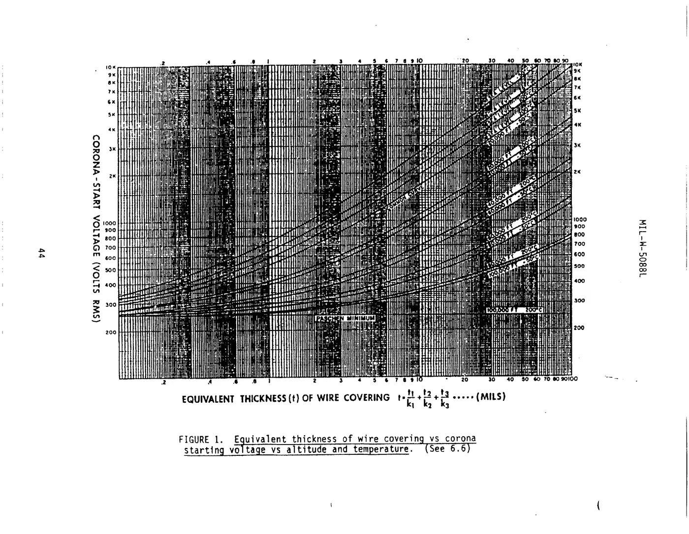
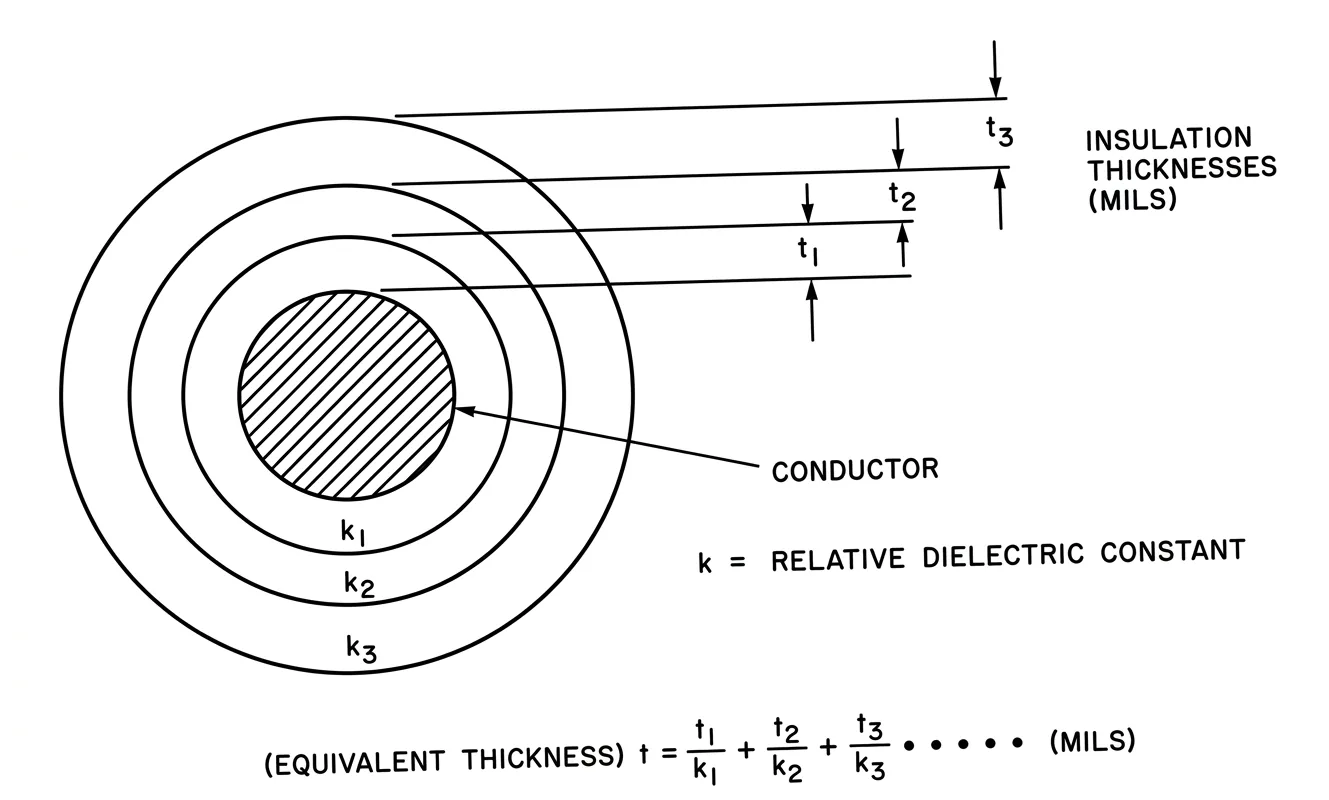
View the original scan (spec page 45)
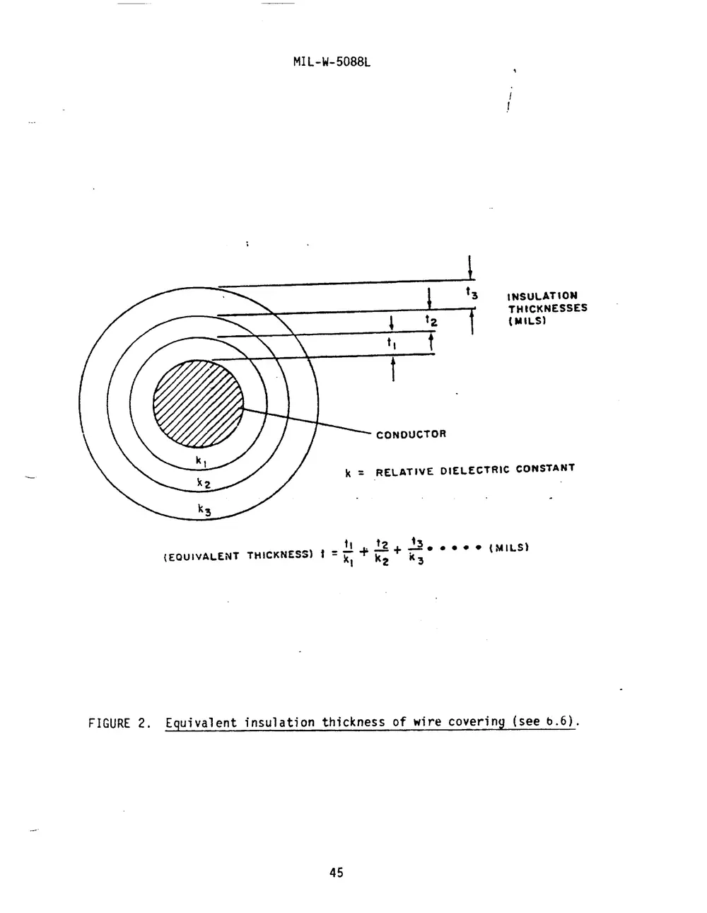
FIGURE 3. Single copper wire in free air
View the original scans (spec pages 46 and 47)
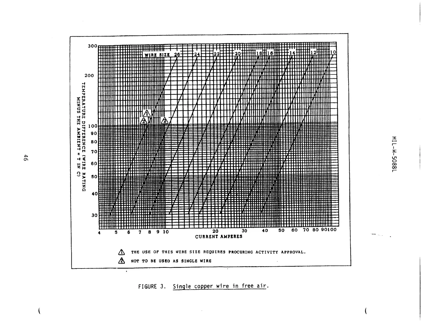
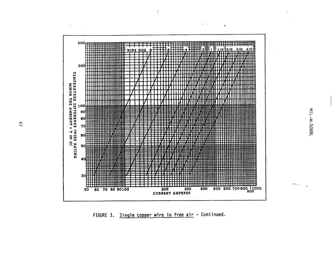
FIGURE 4. Bundle derating curves
View the original scan (spec page 48)
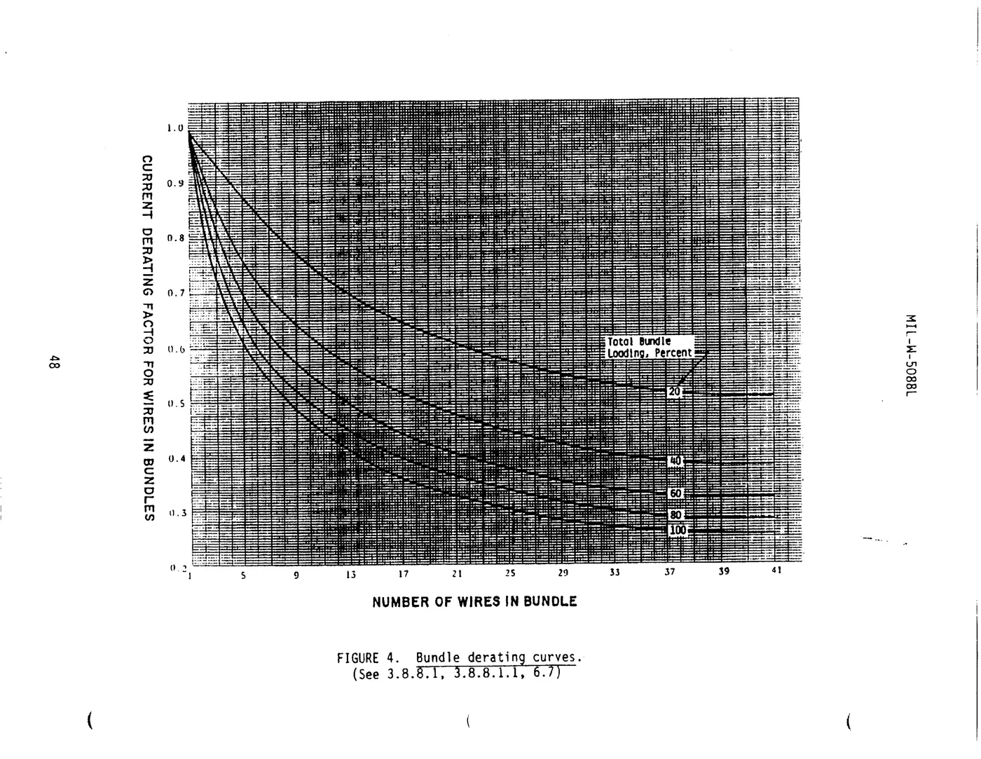
FIGURE 5. Altitude derating curve
View the original scan (spec page 49)
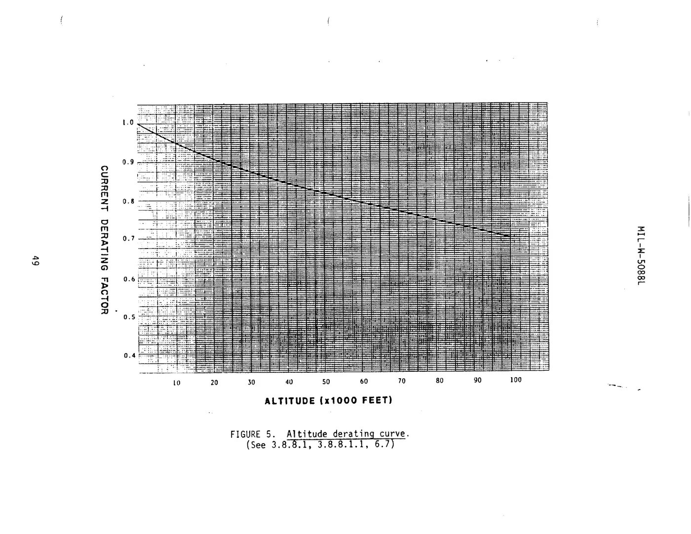
Figures 3, 4 and 5 together give a wire's allowable current. Run them for your own current, temperature, bundle and altitude in the Wire & Harness Sizing Calculator instead of reading all three charts by hand.
APPENDIX A
OPEN OR PROTECTED HARNESSES
10. SCOPE
10.1 Scope. This appendix governs the selection of electric wire and cable to be used for the interconnection of equipment in aerospace vehicles. This Appendix is a mandatory part of the specification. The information contained herein is intended for compliance.
20. APPLICABLE DOCUMENTS
20.1 Government documents.
20.1.1 Specifications, standards and handbooks. Unless otherwise specified, the following specifications, standards and handbooks of the issue listed in that issue of the Department of Defense Index of Specifications and Standards (DODISS) specified in the solicitation form a part of this specification to the extent specified herein.
SPECIFICATIONS
MILITARY
| MIL-C-17 | Cable, Radio Frequency, Flexible and Semi-Rigid, General Specification for |
| MIL-W-22759 | Wire, Electric, Fluoropolymer-Insulated, Copper or Copper Alloy |
| MIL-W-25038 | Wire, Electrical, High Temperature and Fire Resistant, General Specification For |
| MIL-C-27500 | Cable, Power, Electrical and Cable Special Purpose, Electrical Shielded and Unshielded, General Specification For |
| MIL-W-81044 | Wire, Electric, Crosslinked Polyalkene, Cross-linked Alkane-imide Polymer or Polyarylene Insulated, Copper or Copper Alloy |
| MIL-W-81381 | Wire, Electric, Polyimide-insulated, Copper and Copper Alloy |
| MIL-T-81490 | Transmission Lines, Transverse Electromagnetic Mode |
| MIL-C-85485 | Cable, Electric, Filter Line, Radio Frequency Absorptive |
(Unless otherwise indicated, copies of federal and military specifications, standards and handbooks are available from the Standardization Documents Order Desk, Bldg. 4D, 700 Robbins Avenue, Philadelphia, PA 19111-5094.)
30. REQUIREMENTS
30.1 Selection of wire and cable. Unless otherwise approved by the procuring activity, only wires and cables conforming to one of the documents listed in table A-I, table A-II, 30.1.3, 30.1.4, 30.1.5, 30.1.6, of this Appendix shall be used for interconnection of electric and electronic equipment in aerospace vehicles. The limitations and other selection criteria of Section 3 of this specification shall also be imposed on the selection and use of these wires and cables. The contractor shall become familiar with all requirements of this specification before any wires and cables are selected for use.
30.1.1 Harness wiring. Wires shall be selected from table A-I.
* 30.1.2 Protected harnesses. Wires shall be selected from table A-II, but may also include wires from table A-I. Any harness that uses wire selected from table A-II shall have an outer covering throughout its length for mechanical protection.
* 30.1.3 Use of MIL-W-81381 wire (for Air Force applications only). MIL-W-81381 wire shall be used only when justified to and approved by the responsible program management office within the procuring activity.
* 30.1.4 Cable. Cable shall be in accordance with MIL-C-27500. Only constructions utilizing basic wires in accordance with tables A-I and A-II shall be used. Shielded unjacketed cables shall not be used.
30.1.5 Coaxial cable. Coaxial cable shall be in accordance with MIL-C-17.
30.1.5.1 T.E.M. transmission lines. Transverse electromagnetic mode transmission lines shall be in accordance with MIL-T-81490.
30.1.6 Filter line cable. Radio absorptive filter line cable shall be in accordance with MIL-C-85485.
40. NOTES
40.1 Intended purpose. The purpose of this Appendix is to present the contractor with a working list of approved documents to be used in the selection of wire and cable for aerospace vehicle wiring.
| Document | Voltage rating (maximum) | Rated wire temperature (°C) | Insulation type | Conductor type | Application |
|---|---|---|---|---|---|
| MIL-W-22759/1 | 600 | 200 | Fluoropolymer insulated TFE and TFE coated glass | Silver coated copper | Approved for use in Army, Navy and Air Force applications |
| MIL-W-22759/2 | 600 | 260 | Fluoropolymer insulated TFE and TFE coated glass | Nickel coated copper | Approved for use in Army, Navy and Air Force applications |
| MIL-W-22759/3 | 600 | 260 | Fluoropolymer insulated TFE-glass-TFE | Nickel coated copper | Approved for use in Army, Navy and Air Force applications |
| MIL-W-22759/4 | 600 | 200 | Fluoropolymer insulated TFE-glass-FEP | Silver coated copper | Approved for use in Army, Navy and Air Force applications |
| MIL-W-22759/5 | 600 | 200 | Fluoropolymer insulated extruded TFE | Silver coated copper | Approved for use in Army, Navy and Air Force applications |
| MIL-W-22759/6 | 600 | 260 | Fluoropolymer insulated extruded TFE | Nickel coated copper | Approved for use in Army, Navy and Air Force applications |
| Spec page 54 | |||||
| MIL-W-22759/7 | 600 | 200 | Fluoropolymer insulated extruded TFE | Silver coated copper | Approved for use in Army, Navy and Air Force applications |
| MIL-W-22759/8 | 600 | 260 | Fluoropolymer insulated extruded TFE | Nickel coated copper | Approved for use in Army, Navy and Air Force applications |
| MIL-W-22759/9 | 1000 | 200 | Fluoropolymer insulated extruded TFE | Silver coated copper | Approved for use in Army, Navy and Air Force applications |
| MIL-W-22759/10 | 1000 | 260 | Fluoropolymer insulated extruded TFE | Nickel coated copper | Approved for use in Army, Navy and Air Force applications |
| MIL-W-22759/13 | 600 | 135 | Fluoropolymer insulated FEP PVF2 | Tin coated copper | Approved for use in Army, Navy and Air Force applications |
| MIL-W-22759/16 | 600 | 150 | Fluoropolymer insulated extruded ETFE | Tin coated copper | Approved for use in Army, Navy and Air Force applications |
| Spec page 55 | |||||
| MIL-W-22759/17 | 600 | 150 | Fluoropolymer insulated extruded ETFE | Silver coated high strength copper alloy | Approved for use in Army, Navy and Air Force applications |
| MIL-W-22759/20 | 1000 | 200 | Fluoropolymer insulated extruded TFE | Silver coated high strength copper alloy | Approved for use in Army, Navy and Air Force applications |
| MIL-W-22759/21 | 1000 | 260 | Fluoropolymer insulated extruded TFE | Nickel coated high strength copper alloy | Approved for use in Army, Navy and Air Force applications |
| MIL-W-22759/34 | 600 | 150 | Fluoropolymer insulated crosslinked modified ETFE | Tin coated copper | Approved for use in Army, Navy and Air Force applications |
| MIL-W-22759/35 | 600 | 200 | Fluoropolymer insulated crosslinked modified ETFE | Silver coated high strength copper alloy | Approved for use in Army, Navy and Air Force applications |
| MIL-W-22759/41 | 600 | 200 | Fluoropolymer insulated crosslinked modified ETFE | Nickel coated copper | Approved for use in Army, Navy and Air Force applications |
| Spec page 56 | |||||
| MIL-W-22759/42 | 600 | 200 | Fluoropolymer insulated crosslinked modified ETFE | Nickel coated high strength copper alloy | Approved for use in Army, Navy and Air Force applications |
| MIL-W-22759/43 | 600 | 200 | Fluoropolymer insulated crosslinked modified ETFE | Silver coated copper | Approved for use in Army, Navy and Air Force applications |
| MIL-W-25038/3 2/ | 600 | 260 | See specification sheet | See specification sheet | Approved for use in Army, Navy and Air Force applications |
| MIL-W-81044/6 | 600 | 150 | Crosslinked polyalkene | Tin coated copper | Approved for use in Army, Navy and Air Force applications |
| MIL-W-81044/7 | 600 | 150 | Crosslinked polyalkene | Silver coated high strength copper alloy | Approved for use in Army, Navy and Air Force applications |
| MIL-W-81044/9 | 600 | 150 | Crosslinked polyalkene | Tin coated copper | Approved for use in Army, Navy and Air Force applications |
| Spec page 57 | |||||
| MIL-W-81044/10 | 600 | 150 | Crosslinked polyalkene | Silver coated high strength copper alloy | Approved for use in Army, Navy and Air Force applications |
| MIL-W-81381/11 | 600 | 200 | Fluorocarbon polyimide | Silver coated copper | Army: Not for use Navy: Not for use Air Force: 3/ |
| MIL-W-81381/12 | 600 | 200 | Fluorocarbon polyimide | Nickel coated copper | Army: Not for use Navy: Not for use Air Force: 3/ |
| MIL-W-81381/13 | 600 | 200 | Fluorocarbon polyimide | Silver coated high strength copper alloy | Army: Not for use Navy: Not for use Air Force: 3/ |
| MIL-W-81381/14 | 600 | 200 | Fluorocarbon polyimide | Nickel coated high strength copper alloy | Army: Not for use Navy: Not for use Air Force: 3/ |
| MIL-W-81381/22 | 600 | 150 | Fluorocarbon polyimide | Tin coated copper | Army: Not for use Navy: Not for use Air Force: 3/ |
| 1/ For sealing capability of wire, see 3.8.6 and 3.14.1. 2/ For use in circuits where during a fire, maintenance of electrical integrity is required for a limited time. 3/ MIL-W-81381 is allowed in Air Force applications only (See 30.1.3 for restrictions). | |||||
| Document | Voltage rating (maximum) | Rated wire temperature (°C) | Insulation type | Conductor type | Application |
|---|---|---|---|---|---|
| MIL-W-22759/11 | 600 | 200 | Fluoropolymer insulated extruded TFE | Silver coated copper | Approved for use in Army, Navy and Air Force applications |
| MIL-W-22759/12 | 600 | 260 | Fluoropolymer insulated extruded TFE | Nickel coated copper | Approved for use in Army, Navy and Air Force applications |
| MIL-W-22759/14 | 600 | 135 | Fluoropolymer insulated FEP-PVF2 | Tin coated copper | Approved for use in Army, Navy and Air Force applications |
| MIL-W-22759/15 | 600 | 135 | Fluoropolymer insulated FEP-PVF2 | Silver plated high strength copper alloy | Approved for use in Army, Navy and Air Force applications |
| MIL-W-22759/18 | 600 | 150 | Fluoropolymer insulated extruded ETFE | Tin coated copper | Approved for use in Army, Navy and Air Force applications |
| MIL-W-22759/19 | 600 | 150 | Fluoropolymer insulated extruded ETFE | Silver coated high strength copper alloy | Approved for use in Army, Navy and Air Force applications |
| Spec page 59 | |||||
| MIL-W-22759/22 | 600 | 200 | Fluoropolymer insulated extruded TFE | Silver coated high strength copper alloy | Approved for use in Army, Navy and Air Force applications |
| MIL-W-22759/23 | 600 | 260 | Fluoropolymer insulated extruded TFE | Nickel coated high strength copper alloy | Approved for use in Army, Navy and Air Force applications |
| MIL-W-22759/32 | 600 | 150 | Fluoropolymer insulated crosslinked modified ETFE | Tin coated copper | Approved for use in Army, Navy and Air Force applications |
| MIL-W-22759/33 | 600 | 200 | Fluoropolymer insulated crosslinked modified ETFE | Silver coated high strength copper alloy | Approved for use in Army, Navy and Air Force applications |
| MIL-W-22759/44 | 600 | 200 | Fluoropolymer insulated crosslinked modified ETFE | Silver coated copper | Approved for use in Army, Navy and Air Force applications |
| MIL-W-22759/45 | 600 | 200 | Fluoropolymer insulated crosslinked modified ETFE | Nickel coated copper | Approved for use in Army, Navy and Air Force applications |
| Spec page 60 | |||||
| MIL-W-22759/46 | 600 | 200 | Fluoropolymer insulated crosslinked modified ETFE | Nickel coated high strength copper alloy | Approved for use in Army, Navy and Air Force applications |
| MIL-W-81044/12 | 600 | 150 | Crosslinked polyalkene | Tin coated copper | Approved for use in Army, Navy and Air Force applications |
| MIL-W-81044/13 | 600 | 150 | Crosslinked polyalkene | Silver coated high strength copper alloy | Approved for use in Army, Navy and Air Force applications |
| MIL-W-81381/7 | 600 | 200 | Fluorocarbon polyimide | Silver coated copper | Army: Not for use Navy: Not for use Air Force: 2/ |
| MIL-W-81381/8 | 600 | 200 | Fluorocarbon polyimide | Nickel coated copper | Army: Not for use Navy: Not for use Air Force: 2/ |
| MIL-W-81381/9 | 600 | 200 | Fluorocarbon polyimide | Silver coated high strength copper alloy | Army: Not for use Navy: Not for use Air Force: 2/ |
| MIL-W-81381/10 | 600 | 200 | Fluorocarbon polyimide | Nickel coated high strength copper | Army: Not for use Navy: Not for use Air Force: 2/ |
| Spec page 61 | |||||
| MIL-W-81381/17 | 600 | 200 | Fluorocarbon polyimide | Silver coated copper | Army: Not for use Navy: Not for use Air Force: 2/ |
| MIL-W-81381/18 | 600 | 200 | Fluorocarbon polyimide | Nickel coated copper | Army: Not for use Navy: Not for use Air Force: 2/ |
| MIL-W-81381/19 | 600 | 200 | Fluorocarbon polyimide | Silver coated high strength copper alloy | Army: Not for use Navy: Not for use Air Force: 2/ |
| MIL-W-81381/20 | 600 | 200 | Fluorocarbon polyimide | Nickel coated high strength copper alloy | Army: Not for use Navy: Not for use Air Force: 2/ |
| MIL-W-81381/21 | 600 | 150 | Fluorocarbon polyimide | Tin coated copper | Army: Not for use Navy: Not for use Air Force: 2/ |
| 1/ For sealing capability of wire, see 3.8.6 and 3.14.1. 2/ MIL-W-81381 is allowed for use in Air Force applications only (See 30.1.3 for restrictions). | |||||
APPENDIX A — THIS PAGE INTENTIONALLY LEFT BLANK
APPENDIX B
SIGNIFICANT WIRE IDENTIFICATION
(See 3.9.1)
10. SCOPE
10.1 Scope. This appendix establishes the procedure for assigning the identification codes for each individual wire and harness within the scope of this specification when the type of identification code is specified as "significant" in accordance with 3.9.1 and 6.2. The wire identification is "significant" in that it indicates the function of the circuit. This identification shall be for use in wiring data and for physical identification of installed wiring. This Appendix is a mandatory part of the specification. The information contained herein is intended for compliance.
20. APPLICABLE DOCUMENTS
20.1 Government documents.
* 20.1.1 Specifications, standards and handbooks. The following specifications, standards, and handbooks form a part of this document to the extent specified herein. Unless otherwise specified, the issues of these documents are those listed in the issue of the Department of Defense Index of Specifications and Standards (DODISS) and the supplement thereto, cited in the solicitation.
STANDARDS
MILITARY
| MIL-STD-196 | Joint Electronics Type Designation System |
(Unless otherwise indicated, copies of federal and military specifications, standards and handbooks are available from the Standardization Documents Order Desk, Bldg. 4D, 700 Robbins Avenue, Philadelphia, PA 19111-5094.)
30. REQUIREMENTS
30.1 Assignment responsibility. The contractor (installing activity) shall assign the identification code for circuit functions except those listed under R, S, T and Y in Table B-I. The equipment contractor shall assign the identification code in accordance with the equipment specification for equipments falling under categories R, S, T and Y.
30.2 Wiring identification code. The wiring identification code shall be in accordance with the pattern illustrated in Figure B-1 or B-2 as applicable, and as follows:
30.3 Unit number. Where two or more identical items of equipment are installed in the same vehicle, the unit numbers "1," "2," "3," "4," etc., may be prefixed to differentiate between wires when it is desired that the equipment have the same basic identification. To facilitate interchangeability requirements, identical wiring located in left and right wings, nacelles, and major interchangeable structural assemblies may have identical identification and the unit number is not required.
30.4 Circuit function letter. The circuit function letter is used to identify the circuit function specified in Table B-I. Where a wire is used for more than one circuit function, the circuit function letter of that circuit which is functionally predominant shall apply. When functional predominance is questionable, the circuit function letter for the wire having the lowest wire number shall be used.
30.5 Wire number. The wire number consisting of one or more digits is used to differentiate between wires in the circuit. A different number shall be used for wire not having a common terminal or connection.
30.5.1 Wires with the same circuit function having a common terminal connection or junction shall have the same wire number but different segment letters.
30.5.2 Numbers 2000 to 4999, inclusive, shall be reserved for use by the procuring activity to identify wires installed by service modifications.
30.5.3 Beginning with the lowest number, a number shall be assigned to each wire in numerical sequence, as far as practicable.
30.6 Wire segment letter. A wire segment is a conductor between two terminals or connections. The wire segment letter is used to differentiate between conductor segments in a particular circuit. A different letter shall be used for wire segments having a common terminal or connection. Wire segments shall be lettered in alphabetical sequence and the letter "A" should identify the first segment of each circuit starting at the power source. If a circuit contains only one wire segment, the wire segment shall be marked "A." The letters "I" and "O" shall not be used as segment letters. Double letters "AA," "AB," "AC," etc., shall be used when more than 24 segments are required. Two permanently spliced wires do not require separate segment letters if the splice is used for modification or repair.
30.7 Wire size number. The wire size number is used to identify the size of the wire or cable. For coaxial wires and thermocouple wires, the wire size number shall not be included. For thermocouple wires, a dash (-) shall be used in lieu of the wire size number.
30.8 Ground, phase or thermocouple letter(s).
30.8.1 Unless otherwise specified by the procuring activity, ground cable letter "N" shall be used as a suffix to the wire identification code to identify any wiring that completes the circuit to the ground network. Such wiring shall be capable of being connected to the ground network of the aircraft electrical system without causing malfunctioning of any circuit. Critical and sensitive electronic systems which have interconnecting "ground" leads, but only one segment actually grounded to the structure shall be identified with the "N" suffix.
30.8.2 Phase letter "A," "B" or "C" shall be used as a suffix on the wire identification code to identify the phase of wires that are in the three-phase power distribution wiring of AC systems. The phase sequence shall be "A-B-C." The letters "A," "B" and "C" shall indicate the phase sequence corresponding to "T1," "T2" and "T3," respectively. For grounded delta
systems, "T2" shall be considered as corresponding to the grounded phase. (Examples of wire identification coding, as applied to AC power wiring, are illustrated by Figure B-3.)
30.8.3 Phase letter "V" shall be used as a suffix on the identification code to identify the ungrounded wire that is in a single-phase system.
30.8.4 For thermocouple wire, the following suffixes shall be used as applicable. Where space considerations dictate, the two letter suffixes shown may be used:
| CHROM | Chromel | CR |
| ALML | Alumel | AL |
| IRON | Iron | FE |
| CONST | Constantan | CN |
| COP | Copper | CU |
* 30.9 Electromagnetic Compatibility (EMC) identification. When EMC category number identification is used, it shall be accomplished by marking applicable category number at the end of each significant wire code. Category number definition shall be as specifically approved by the procuring activity.
* 30.9.1 Alternate methods for EMC identification. Alternate methods such as identification sleeving, color codes or other methods may be used for EMC category identification when approved by procuring activity.
30.10 Aluminum wire. For aluminum wire, ALUMINUM or ALUM shall be added as a suffix to the wire identification code.
30.11 Spare contacts. Wires attached to spare contacts of connectors shall be identified by the contact designation.
30.12 Harnesses. Each harness shall be identified by the letter "W" and a distinct suffix. Example: W-1, W-2, W-3, W-4, etc.
30.13 Code for type designated equipment. For equipment type designated in accordance with MIL-STD-196, the wire identification code shall be derived utilizing that portion of the military type designation (AN nomenclature) following the /, but excluding the hyphen and any suffix letters. The block of wire numbers for each equipment shall start with 1 and continue for as many numbers as are needed to identify all wires. For example, wires of an AN/APS-45 would be identified APS45-1A20 --- APS45-975C22; wires of the AN/ARC-52A would be ARC52-1A22 --- ARC52-999C22; and the MX94 would be the MX94-1A20 --- MX94-62D20.
| Circuit function letter | Circuit | Examples |
|---|---|---|
| A | Armament | Stores Management System Missiles/Rockets Gun Chemical |
| B | Photographic | Camera Camera Doors Camera Heating |
| C | Control Surface | Autopilot Flight Control Wing Sweep Trim Control Airbrakes Hydraulic System |
| D | Instrument (other than flight or engine instruments) | Position Indicator Pressure Gauge Temperature Gauge Clock |
| E | Engine Instrument | Temperature Gauge Pressure Gauge Quantity Meter Flow Meter Tachometer Power Indicator Nozzle Indicator |
| F | Flight Instrument | Gyroscopic Instrument Attitude Indicator Compass Head Up Display Altitude |
| G | Landing Gear Wing Folding | Extension and Retraction Braking Locking Steering Anti-Skid Arrestor Hook Utilities Hydraulics |
| Spec page 68 | ||
| H | Heating Ventilating and De-icing | Heating De-icing Cabin conditioning Galley Equipment Bay Cooling |
| I | In order to avoid confusion with the numeral one, the letter "I" shall not be used for circuit or cable identification. | |
| J | Ignition | Engine Ignition Jet-Assisted Take-Off |
| K | Engine Control | Vent and Flap Propeller Control Carburetor Supercharging Power Control Nozzle Control Thrust Reverser Engine Starting |
| L | Lighting (Illumination) | Internal External |
| M | Miscellaneous (Electrical) | Windshield Wiper & Spray Doors Hoist and Winch Position (Seat & Pedal) Auxiliary Power Unit Emergency Power Unit Cigarette Lighter |
| N | Unassigned | |
| O | In order to avoid confusion with the numeral zero, the letter "O" shall not be used for circuit or cable identification. | |
| P | DC Power | Generation Distribution Battery Rectifier External Power |
| Spec page 69 | ||
| Q | Fuel and Oil | Valves Pumps Refueling/Defueling Transfer Dump |
| R | Radio (Navigational and Communication) | Instrument Landing Homing Liaison Marker Beacon VHF Radio UHF Radio HF Radio Intercommunication Direction Finding |
| S | Radar (Pulse Technique) | Radar Altimeter Interception Gun Aiming Mapping Navigation Bomb Aiming Search Recognition (IFF) Terrain Following |
| T | Special Electronics | Active Electronic Counter Inertial Navigation Television Measures Reconnaissance Computer Weapon Aiming Chaff Dispensing Infra-Red |
| U | Miscellaneous (Electronic) | Electronic wiring for which the "R," "S" or "T" identification is not applicable shall be assigned the circuit function letter "U." An example would be common leads to electronic equipments and systems, interconnection wiring, such as antenna or power circuits common to more than one equipment. |
| Spec page 70 | ||
| V | Both DC power cables and DC control cables for AC systems shall be identified by the circuit function letter "V." | |
| W | Warning and Emergency (except those listed under other circuit functions) | Bail-Out Alarm Oxygen Indicator Passenger Sign Central/Master Warning |
| X | AC Power | Generation Distribution External Power |
| Y | Armament Special Equipment (except those listed under circuit function "A") | |
| Z | Experimental Circuits. When flight test and experimental research wiring is installed, the appropriate Circuit Function Letter shall be used, preceded by the letter "Z." When any such circuit has been adopted and becomes part of a standard installation, the letter "Z" shall be removed. | |
APPENDIX B — THIS PAGE INTENTIONALLY LEFT BLANK
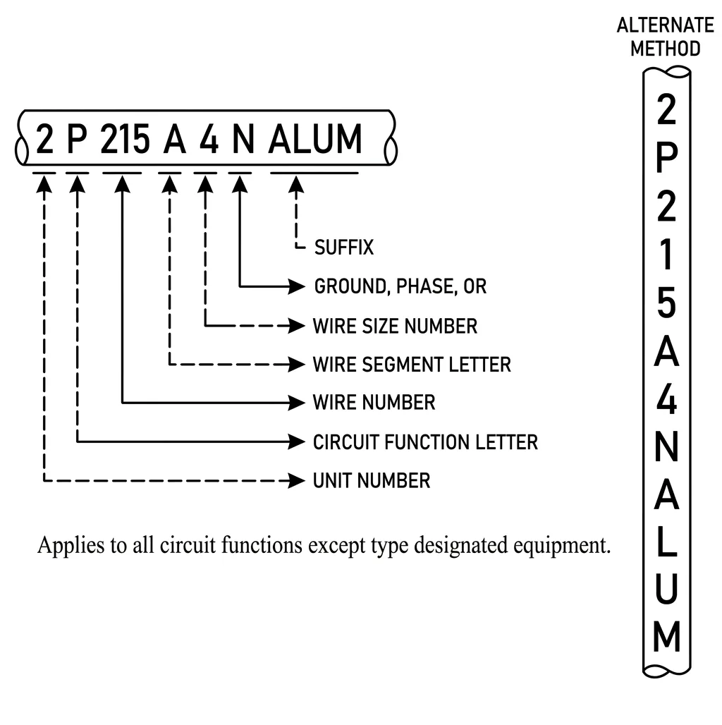
- 2 Unit number
- P Circuit function letter
- 215 Wire number
- A Wire segment letter
- 4 Wire size number
- N Ground, phase, or thermocouple letter
- ALUM Suffix
View the original scan (spec page 71)
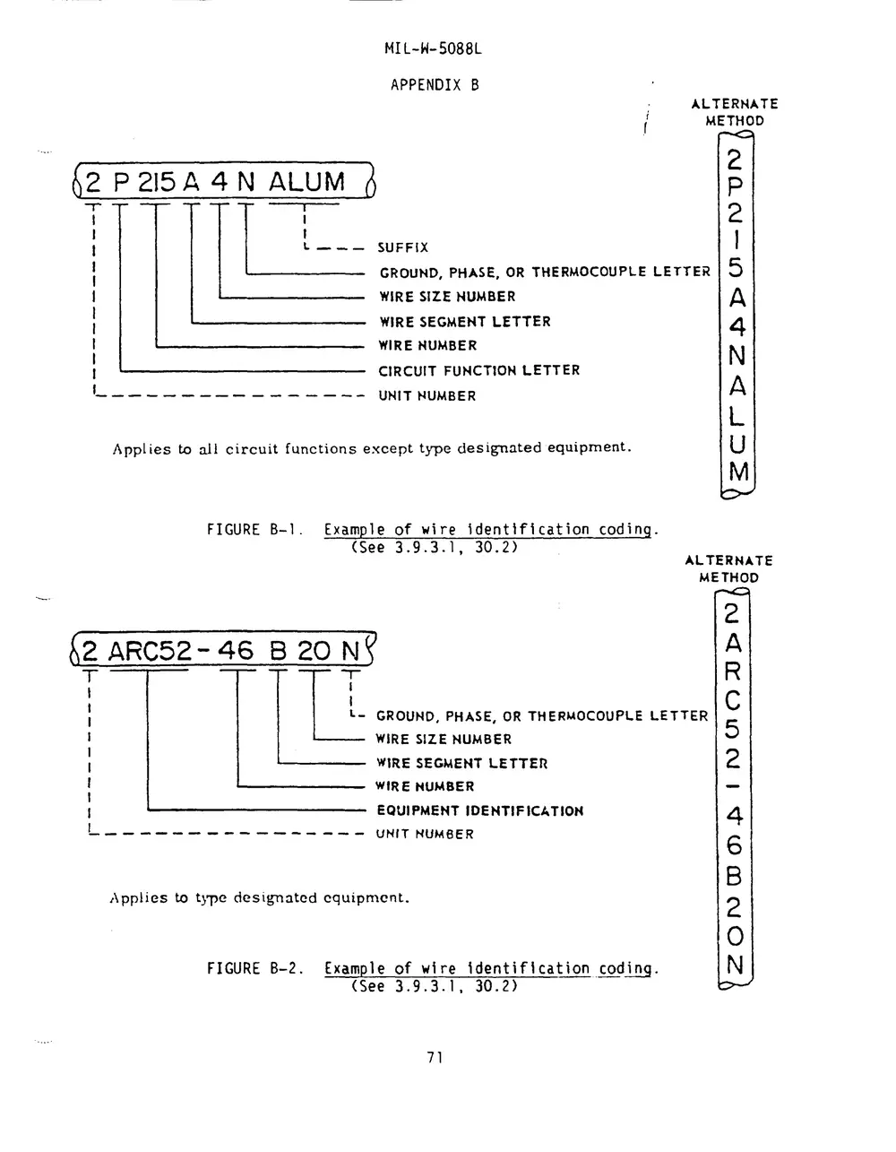
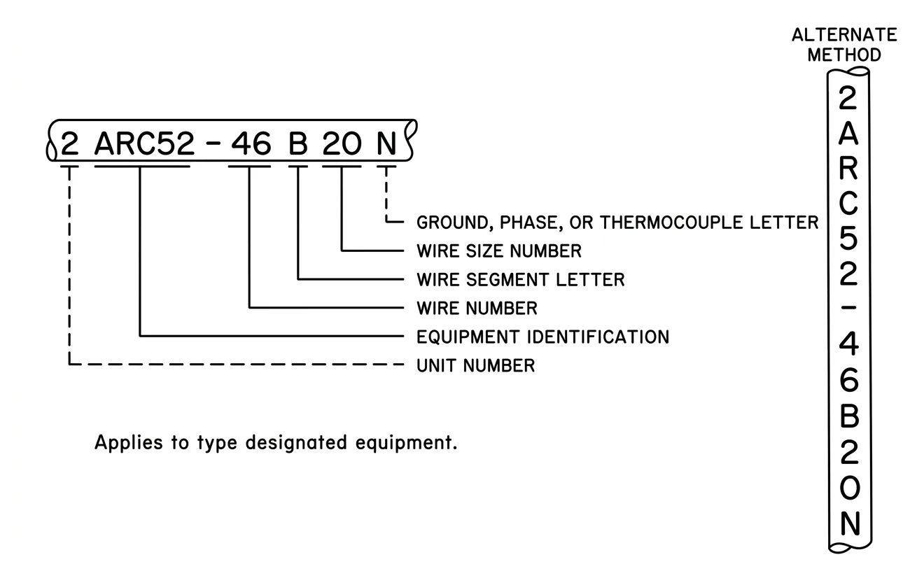
- 2 Unit number
- ARC52 Equipment identification
- 46 Wire number
- B Wire segment letter
- 20 Wire size number
- N Ground, phase, or thermocouple letter
View the original scan (spec page 71)
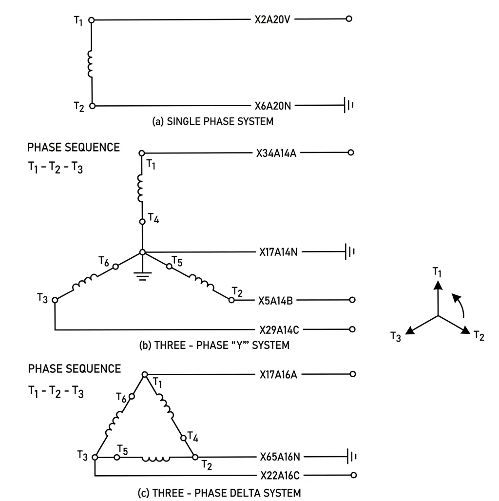
View the original scan (spec page 72)
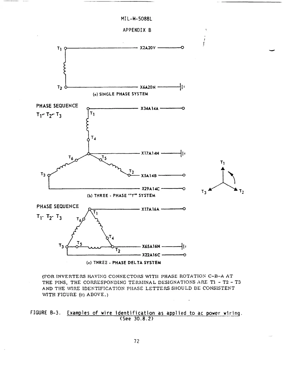
APPENDIX C
NON-SIGNIFICANT WIRE IDENTIFICATION
(See 3.9.1)
10. SCOPE
10.1 Scope. This appendix establishes the procedure for assigning the individual codes for each wire, cable and harness within the scope of this specification when the type of identification code is specified as "non-significant" in accordance with 3.9.1 and 6.2. The wire identification is "non-significant" in that it does not indicate the function of the circuit. This identification shall be for use in wiring data and for physical identification of installed wiring. This appendix is a mandatory part of the specification. The information contained herein is intended for compliance.
20. APPLICABLE DOCUMENTS
This section is not applicable to this appendix.
30. REQUIREMENTS
30.1 Harness identification. Each harness shall be identified by the class letter "W" followed by a distinct wire harness number identifier of not more than four digits.
30.2 Wire identification. Each wire shall be assigned a unique alpha-numeric identification (wire number) to distinguish it from all other wires in the aerospace vehicle. Each wire number shall include the wire harness identification, a wire identifier, a wire gage number and where applicable, special coding for wire color, thermocouple wire and shields.
Example:
- (a) W Wire harness class letter.
- (b) 192 Wire harness number identifier (maximum of 4 digits, see 30.1).
- (c) 06 Wire identifier (maximum of 4 digits, see 30.2.1).
- (d) 22 Wire gage number (see 30.2.2).
- (e) XX Special coding (see 30.2.3).
- (f) - Hyphen separation.
The wire number will read "W192-06-22XX".
30.2.1 Wire identifier. The wire identifier shall distinguish each wire from all others within a given harness. Harness to harness continuity of the wire identifier is a requirement for wires joined by splices. Harness to harness continuity of the wire identifier is not a requirement for all other wires but should be considered as a design objective. The wire identifier shall not exceed four digits.
30.2.1.1 Wire identifiers 900 to 999 and 9000 to 9999 inclusive, shall be researched for use by the procuring activity to identify wires installed by service modifications.
30.2.2 Wire gage number. The wire gage number identifies the wire size. For coaxial cables and thermocouple wires, the wire gage may be omitted from the wire identification.
30.2.3 Special coding.
30.2.3.1 Thermocouple wire. For thermocouple wire, the following letter codes shall be used as applicable:
| Chromel | CR |
| Alumel | AL |
| Iron | FE |
| Constantan | CN |
| Copper | CU |
Example: W192-645-CR
30.2.3.2 Color-coded cable. Jacketed, shielded and/or twisted conductor cable consisting of 2 or more wires which are color coded by single strips or bands or by solid colors shall be assigned the same wire identifier. The color of each conductor shall be identified by using the two letter code shown below following the wire gauge number.
| Color | Letter code |
|---|---|
| Black | BK |
| Brown | BR |
| Red | RD |
| Orange | OR |
| Yellow | YE |
| Green | GN |
| Color | Letter code |
|---|---|
| Blue | BL |
| Violet | VT |
| Gray | GY |
| White | WH |
| Pink | PK |
See the example in 30.2.3.3 for a shielded, tri-conductor, color-coded cable.
30.2.3.3 Shields. Shielded cable having common wire identifiers assigned in accordance with 30.2.3.2 shall be assigned the same number as the conductor(s). Shields over complete harnesses or over groups of wires having different wire identifiers assigned in accordance with 30.2.1 shall be assigned separate wire identifiers. The suffix "SH" shall follow the "wire-identifier."
- Example of a shield over wires separately identified in accordance with 30.2.1:
W192-019-22
W192-020-22
W192-600-SH
- Example of a shielded single conductor:
W201-019-22
W201-019-SH
- Example of a shielded, color-coded tri-conductor:
W201-363-22 RD
W201-362-22 BL
W201-362-22 YE
W201-362-SH
30.2.3.4 Aluminum wire. For aluminum wire, "ALUM" (if total number of digits exceeds 15, "AM" shall be used) shall be added as a suffix to the wire identification code.
APPENDIX C — THIS PAGE INTENTIONALLY LEFT BLANK
BACK MATTER
Index, referenced documents index and DD Form 1426
Pages 77 to 80 are the keyword index of the specification, pages 81 and 82 are the referenced documents index (each cited document with the paragraphs that cite it), and page 83 is the DD Form 1426 Standardization Document Improvement Proposal. These pages are page-number lookups into the printed original. On this page every section has a permanent link and the page has a search box, so they are provided here as scans only.
View the back-matter scans (spec pages 77 to 83)