In the design of metallurgical joints, the strength of the joining material (for example, weld metal) and the adjacent parent material must be considered. The joint should be analyzed on the basis of its loading, the specified allowable strengths, dimensions and geometry.
The allowable strength for both the adjacent parent metal and the weld metal is given below in the particular section dealing with the method of forming used, and the material being joined. The following subparagraphs define certain joining processes.
Welding — Welding consists of joining two or more pieces of metal by applying heat, pressure or both, with or without filler material, to produce a localized union through fusion or recrystallization across the joint interface. Examples of common welding processes include: fusion [inert-gas, shielded-arc welding with tungsten electrode (TIG) and inert-gas shielded metal-arc welding using covered electrodes (MIG)], resistance (spot and seam), and flash. Several terms used in describing various sections of a welded joint are illustrated in Figure 8.2.1.
Brazing — Brazing consists of joining metals by the application of heat causing the flow of a thin layer, capillary thickness, of nonferrous filler metal into the space between the pieces. Bonding results from the intimate contact produced by the dissolution of a small amount of base metal in the molten filler metal, without fusion of the base metal.
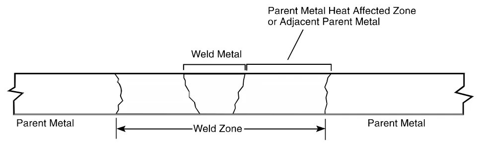
Figure 8.2.1. Schematic diagram of weld and parent metal.
The weld metal section of a joint should be analyzed on the basis of its loading, specified allowable strength, dimensions and geometry. The effects of the parent metal are to be accounted for as specified herein.
Section 9.4.2 contains a detailed discussion of one acceptable method of establishing fusion welding allowables. As stated in that section, other methods can be employed as approved by certifying agencies. The following subsections contain specific information for a number of materials.
Allowable fusion weld-metal strengths of steel alloys are shown in Table 8.2.2.1.1(a). Design allowable stresses for the weld metal are based on 85 percent of the respective minimum tensile ultimate test values.
For steel joints welded after heat treatment, the allowable strengths near the weld are given in Tables 8.2.2.1.1(b) and (c).
For materials heat treated after welding, the allowable strength in the parent metal near a welded joint may equal the allowable strength for the material in the heat treated condition as given in the tables of design mechanical properties of the specific alloys; however, it should be noted that the weld metal allowables are based on 85 percent of these values.
| Material | Heat Treatment Subsequent to Welding | Welding Rod or Electrode | Fsu, ksi | Ftu, ksi |
|---|---|---|---|---|
| Carbon and alloy steels | None | AMS 6457 | 32 | 51 |
| AWSA5.1 classes E6010 and E6013 | 32 | 51 | ||
| Alloy steels | None | AMS 6452 | 43 | 72 |
| Alloy steels | Stress relieved | AWSA5.5 class E10013 MIL-E-22200/10, classes MIL-10018-M1 | 50 | 85 |
| Section Thickness ¼ inch or less | |
|---|---|
| Type of Joint | Ultimate Tensile Stress, ksi |
| Tapered joints of 30° or lessb | 90 |
| All others | 80 |
| a Welded after heat treatment or normalized after weld. | |
| b Gussets or plate inserts considered 0° taper with centerline. | |
| Type of Joint | Bending Modulus of Rupture, ksi |
|---|---|
| Tapered joints of 30° or lessb | Fb from Figure 2.8.1.1 for Ftu = 90 ksi |
| All others | 0.9 of the values of Fb from Figure 2.8.1.1 for Ftu = 90 ksi |
| a Welded after heat treatment or normalized after weld. | |
| b Gussets or plate inserts considered 0° taper with centerline. | |
The ultimate tensile allowable strength and bending allowable modulus of rupture for flash and pressure welds are given in Tables 8.2.2.2(a) and (b). A higher efficiency may be permitted in special cases by the applicable procuring or certifying agency upon approval of the manufacturer’s process specification.
| Tubing | Allowable Ultimate Tensile Stress of Welds |
|---|---|
| Normalized tubing — not heat treated (including normalizing) after welding | 1.0 Ftu (based on Ftu of normalized tubing) |
| Heat-treated tubing welded after heat treatment | 1.0 Ftu (based on Ftu of normalized tubing) |
| Tubing heat treated (including normalizing) after welding. Ftu of unwelded material in heat-treated condition: | |
| < 100 ksi | 0.9 Ftu |
| 100 to 150 ksi | 0.6 Ftu + 30 |
| > 150 ksi | 0.8 Ftu |
| Tubing | Allowable Bending Modulus of Rupture of Welds (Fb from Figure 2.8.1.1 using values of Ftu listed) |
|---|---|
| Normalized tubing — not heat treated (including normalizing after welding | 1.0 Ftu (based on Ftu of normalized tubing) |
| Heat-treated tubing welded after heat treatment | 1.0 Ftu (based on Ftu of normalized tubing) |
| Tubing heat treated (including normalizing) after welding. Ftu of unwelded material in heat-treated condition: | |
| < 100 ksi | 0.9 Ftu |
| 100 to 150 ksi | 0.6 Ftu + 30 |
| > 150 ksi | 0.8 Ftu |
Permission to use spot and seam welding on structural parts is governed by the requirements of the procuring or certifying agency. Table 8.2.2.3 gives the recommended allowable edge distance for spot and seam welds.
| Nominal Thicknessb of Thinner Sheet, inch | Minimum Lap Jointc,d Edge Distance, inch | Minimum Spacinge, inch |
|---|---|---|
| 0.016 | 0.19 | 0.19 |
| 0.020 | 0.20 | 0.30 |
| 0.025 | 0.22 | 0.38 |
| 0.032 | 0.25 | 0.46 |
| 0.040 | 0.28 | 0.52 |
| 0.050 | 0.31 | 0.58 |
| 0.063 | 0.38 | 0.67 |
| 0.071 | 0.41 | 0.73 |
| 0.080 | 0.44 | 0.79 |
| 0.090 | 0.47 | 0.89 |
| 0.100 | 0.50 | 1.00 |
| 0.125 | 0.56 | 1.25 |
| 0.160 | 0.69 | 1.60 |
| a Reference Aluminum Association and American Welding Society Handbook. | ||
| b Intermediate gages will require interpolation between adjacent gages. | ||
| c Edge distances are measured materials in contact; this can be to a free edge or to a sheet metal radius where one material bends away from another. Edge distances less than those specified above may be used provided there is no expulsion of weld material or bulging of the edge of the sheet; however, these joints may have less static strength and shorter fatigue life. | ||
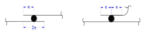
The design shear strength for spot welds for these materials are given in Tables 8.2.2.3.1(a) and (b). The thickness ratio of the thickest sheet to the thinnest outer sheet in the combination should not exceed 4:1.
| Thickness of Thinnest Outer Sheet, in. | Spots/inch | Material Ultimate Tensile Strength, ksi | ||||
|---|---|---|---|---|---|---|
| Standard (Ns)d | Rangee,f | Above 185 | 150 to 185 | 90 to 149 | Below 90 | |
| Design Shear Strength, pounds per linear inch (Xm) | ||||||
| 0.001 | 40 | 1-50 | 72 | 64 | 52 | 36 |
| 0.002 | 20 | 1-30 | 144 | 128 | 104 | 72 |
| 0.003 | 12 | 1-17 | 240 | 208 | 164 | 120 |
| 0.004 | 10 | 1-14 | 324 | 280 | 228 | 152 |
| 0.005 | 9 | 1-13 | 392 | 340 | 272 | 188 |
| 0.006 | 7 | 1-10 | 432 | 380 | 304 | 220 |
| 0.007 | 6 | 1-8 | 504 | 440 | 352 | 256 |
| 0.008 | 5 | 1-7 | 552 | 488 | 392 | 284 |
| a Strength based on 80 percent of minimum values specified in Specification MIL-W-6858. | ||||||
| b The allowable tensile strength of spot-welds is 25 percent of the design shear strength. Higher values may be used, however, if these are substantiated by tests acceptable to the procuring or certifying agency. | ||||||
| c Refers to plain carbon steels containing not more than 0.15 percent carbon, austenitic, heat and corrosion resistant, and precipitation hardening steels. The reduction in strength of spot-welds due to the cumulative effects of time-temperature-stress factors is not greater than the reduction in strength of the parent metal. | ||||||
| d When the number of spots per inch is within 15 percent of the standard spot per inch requirement, the design shear strengths tabulated above will apply. | ||||||
| e When the number of spots differs from the standard spots per inch by 15 percent or greater, but does not exceed the noted range of spots per inch, applicable design strength will be determined as noted below: | ||||||
| Xm/Ns (K) Nr = Xr | ||||||
| where | ||||||
| Xm = design shear strength in accordance with the above table | ||||||
| Ns = standard spots per inch in accordance with the above table | ||||||
| Nr = required spots per inch (production part) | ||||||
| Xr = actual design shear strength requirement | ||||||
| K = 1.15 when number of spots per inch is reduced more than 15 percent of the standard spacing of the above table | ||||||
| K = 0.90 when number of spots is increased more than 15 percent of the standard spacing but within range of the tabular spacing. | ||||||
| f When the number of spots per inch is above the range indicated in the table, the design shear strength will remain constant at the value obtained at the top of the range. | ||||||
| Design Shear Strength, pounds per spot | ||||
|---|---|---|---|---|
| Material Ultimate Tensile Strength, ksi | Above 185 | 150 to 185 | 90 to 149 | Below 90 |
| Nominal thickness of thinner sheet, in.: | ||||
| 0.009 | 160 | 140 | 104 | 80 |
| 0.010 | 196 | 164 | 128 | 92 |
| 0.012 | 280 | 220 | 160 | 120 |
| 0.016 | 384 | 320 | 236 | 172 |
| 0.018 | 472 | 392 | 272 | 200 |
| 0.020 | 508 | 424 | 312 | 224 |
| 0.022 | 584 | 488 | 360 | 264 |
| 0.025 | 696 | 580 | 424 | 320 |
| 0.028 | 820 | 684 | 508 | 372 |
| 0.032 | 1000 | 836 | 620 | 452 |
| 0.036 | 1200 | 1004 | 736 | 552 |
| 0.040 | 1400 | 1168 | 852 | 652 |
| 0.045 | 1680 | 1436 | 1028 | 804 |
| 0.050 | 1960 | 1700 | 1204 | 956 |
| 0.056 | 2304 | 2040 | 1416 | 1168 |
| 0.063 | 2840 | 2472 | 1688 | 1408 |
| 0.071 | 3360 | 2984 | 2028 | 1664 |
| 0.080 | 3880 | 3528 | 2404 | 1964 |
| 0.090 | 4480 | 4072 | 2812 | 2308 |
| 0.100 | 5040 | 4576 | 3200 | 2640 |
| 0.112 | 5600 | 5092 | 3636 | 3036 |
| 0.125 | 6228 | 5664 | 4052 | 3440 |
| a Strength based on 80 percent of minimum values specified in Specification MIL-W-6858. | ||||
| b The allowable tensile strength of spot-welds is 25 percent of the design shear strength. Higher values may be used, however, if these are substantiated by tests acceptable to the procuring or certifying agency. | ||||
| c Refers to plain carbon steels containing not more than 0.15 percent carbon and to austenitic heat and corrosion resistant, precipitation hardening steels. The reduction in strength of spot-welds due to the cumulative effects of time-temperature-stress factors is not greater than the reduction in strength of the parent metal. | ||||
In applications of spot welding where ribs, intercostals, or doublers are attached to sheet, either at splices or at other joints on the sheet panels, the allowable ultimate strength of the spot-welded stainless steel sheet will be determined by multiplying the ultimate tensile strength of the sheet (A or S-value) by the appropriate efficiency factors shown in Figures 8.2.2.3.1.1(a) through (c). Efficiencies for gages under 0.012 will be determined by test.
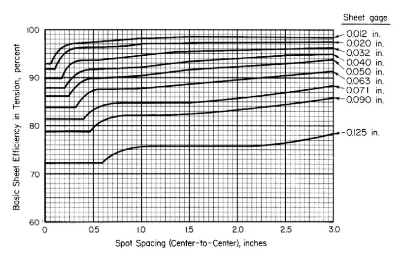
Figure 8.2.2.3.1.1(a). Efficiency of the parent metal in tension for spot-welded AISI 301-A, and AISI 347-A, and AISI 301-1/4 stainless steel.
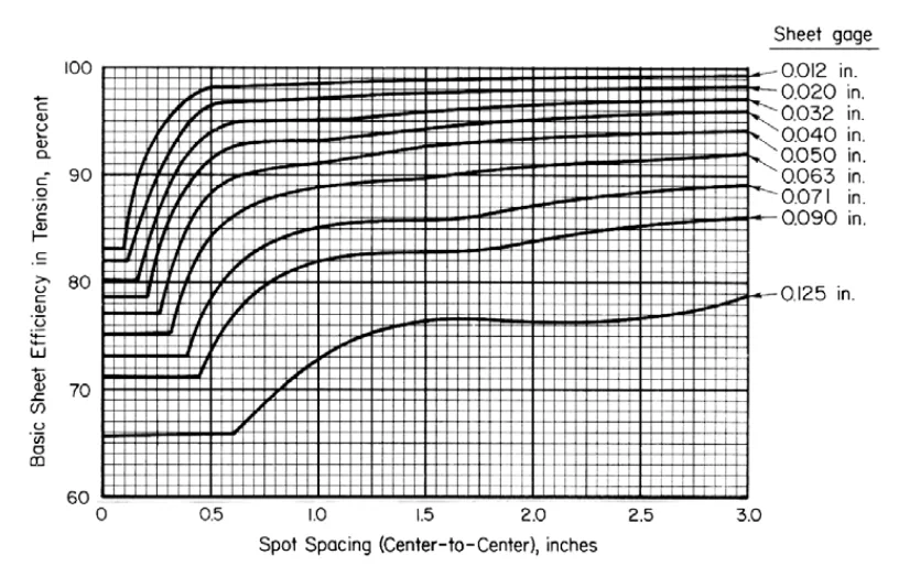
Figure 8.2.2.3.1.1(b). Efficiency of the parent metal in tension for spot-welding AISI 301-1/2H stainless steel.
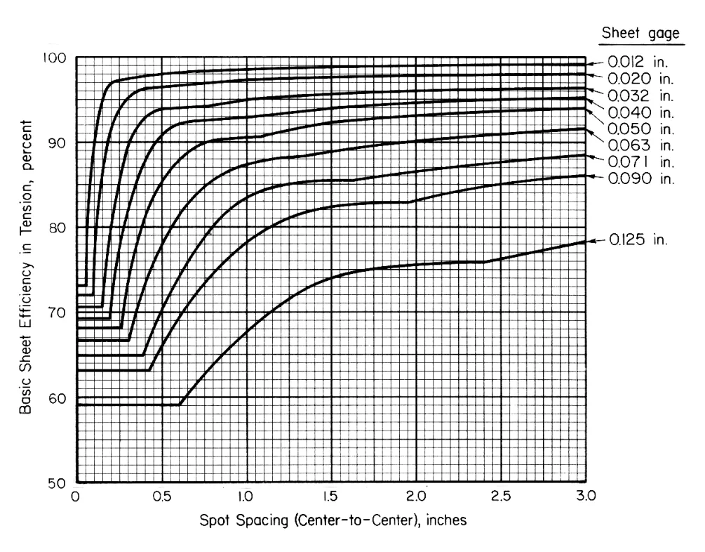
Figure 8.2.2.3.1.1(c). Efficiency of the parent metal in tension for spot-welded AISI 301-H stainless steel.
The acceptable aluminum and aluminum alloy combinations for spot and seam welding are given in Table 8.2.2.3.2(a).
Design shear-strength for spot welds in aluminum alloys are given in Tables 8.2.2.3.2(b) and (c). The thickness ratio of the thickest to the thinnest outer sheet in the combination should not exceed 4:1.
Design shear-strength for spot-welded joints, based on tearing of the sheet, is given in Table 8.2.2.3.2(d) for some aluminum alloys, together with the “maximum” pitches that permit attainment of these strengths. Joints having larger pitches fail in the spot welds rather than by tearing of the sheet, and are governed by Tables 8.2.2.3.2(b) and (c). The design shear strengths listed are also applicable to seam welds.
| Specification | AMS-QQ-A-250/1 | AMS-4029b | AMS-QQ-A-250/3 | AMS-QQ-A-250/4b | AMS-QQ-A-250/5 | AMS-QQ-A-250/2 | AMS-QQ-A-250/8 | AMS-QQ-A-250/11 | AMS-QQ-A-250/12b | AMS-QQ-A-250/13c | |
|---|---|---|---|---|---|---|---|---|---|---|---|
| Material | 1100 | Bare 2014 | Clad 2014 | Bare 2024 | Clad 2024 | 3003 | 5052 | 6061 | Bare 7075 | Clad 7075 | |
| Specification | Material | ||||||||||
| AMS-QQ-A-250/1 | 1100 | ··· | ··· | ··· | ··· | ··· | ··· | ··· | ··· | ··· | ··· |
| AMS-4029 | Bare 2014b | ··· | * | * | * | ··· | ··· | ··· | ··· | * | ··· |
| AMS-QQ-A-250/3 | Clad 2014 | ··· | * | ··· | * | ··· | ··· | ··· | ··· | * | ··· |
| AMS-QQ-A-250/4 | Bare 2024b | ··· | * | * | * | ··· | ··· | ··· | ··· | * | ··· |
| AMS-QQ-A-250/5 | Clad 2024 | ··· | ··· | ··· | ··· | ··· | ··· | ··· | ··· | ··· | ··· |
| AMS-QQ-A-250/2 | 3003 | ··· | ··· | ··· | ··· | ··· | ··· | ··· | ··· | ··· | ··· |
| AMS-QQ-A-250/8 | 5052 | ··· | ··· | ··· | ··· | ··· | ··· | ··· | ··· | ··· | ··· |
| AMS-QQ-A-250/11 | 6061 | ··· | ··· | ··· | ··· | ··· | ··· | ··· | ··· | ··· | ··· |
| AMS-QQ-A-250/12 | Bare 7075b | ··· | * | * | * | ··· | ··· | ··· | ··· | * | ··· |
| AMS-QQ-A-250/13 | Clad 7075b | ··· | ··· | ··· | ··· | ··· | ··· | ··· | ··· | ··· | ··· |
| a The various aluminum and aluminum-alloy materials referred to in this table may be spot-welded in any combinations except the combinations indicated by the asterisk(*) in the table. The combinations indicated by the asterisk (*) may be spot-welded only with the specific approval of the procuring or certifying agency. | |||||||||||
| b This table applies to construction of land- and carrier-based aircraft only. The welding of bare, high-strength alloys in construction of seaplanes and amphibians is prohibited unless specifically authorized by the procuring or certifying agency. | |||||||||||
| c Clad heat-treated and aged 7075 material in thicknesses less than 0.020 inch will not be welded without specific approval of the procuring or certifying agency. | |||||||||||
| Thickness of Thinnest Outer Sheet, in. | Spots/inch | Material Ultimate Tensile Strength, ksi | ||
|---|---|---|---|---|
| Standard (Ns)d | Rangee,f | 56 and Above | Below 56 | |
| Design Shear Strength, pounds per linear inch (Xm) | ||||
| 0.001 | 40 | 1-50 | 24 | 16 |
| 0.002 | 20 | 1-30 | 48 | 32 |
| 0.003 | 12 | 1-17 | 80 | 52 |
| 0.004 | 10 | 1-14 | 108 | 72 |
| 0.005 | 9 | 1-13 | 132 | 92 |
| 0.006 | 7 | 1-10 | 148 | 100 |
| 0.007 | 6 | 1-8 | 168 | 112 |
| 0.008 | 5 | 1-7 | 188 | 128 |
| a The reduction in strength of spot-welds due to the cumulative effects of time-temperature-stress factors is not greater than the reduction in strength of the parent metal. | ||||
| b Strength based on 80 percent of minimum values specified in Specification MIL-W-6858. | ||||
| c The allowable tensile strength of spot-welds is 25 percent of the design shear strength. Higher values may be used, however, if these are substantiated by tests acceptable to the procuring or certifying agency. | ||||
| d When the number of spots per inch is within 15 percent of the standard spot per inch requirement, the design shear strengths tabulated above will apply. | ||||
| e When the number of spots differs from the standard spots per inch by 15 percent or greater, but does not exceed the noted range of spots per inch, applicable design strength will be determined as noted below: | ||||
| Xm/Ns (K) Nr = Xr | ||||
| where | ||||
| Xm = design shear strength in accordance with the above table | ||||
| Ns = standard spots per inch in accordance with the above table | ||||
| Nr = required spots per inch (production part) | ||||
| Xr = actual design shear strength requirement | ||||
| K = 1.15 when number of spots per inch is reduced more than 15 percent of the standard spacing of the above table | ||||
| K = 0.90 when number of spots is increased more than 15 percent of the standard spacing but within range of the tabular spacing. | ||||
| f When the number of spots per inch is above the range indicated in the table, the design shear strength will remain constant at the value obtained at the top of the range. | ||||
| Design Shear Strength, pounds per spot | ||||
|---|---|---|---|---|
| Material Ultimate Tensile Strength, ksi | 56 and Above | 35 to 56 | 19.5 to 34.9 | Below 19.5 |
| Nominal thickness of thinner sheet, in.: | ||||
| 0.010 | 48 | 40 | ··· | ··· |
| 0.012 | 60 | 52 | 24 | 16 |
| 0.016 | 88 | 80 | 56 | 40 |
| 0.018 | 100 | 92 | 68 | 52 |
| 0.020 | 112 | 108 | 80 | 64 |
| 0.022 | 128 | 124 | 96 | 76 |
| 0.025 | 148 | 140 | 116 | 88 |
| 0.028 | 172 | 164 | 140 | 108 |
| 0.032 | 208 | 188 | 168 | 132 |
| 0.036 | 244 | 220 | 204 | 156 |
| 0.040 | 276 | 248 | 240 | 180 |
| 0.045 | 324 | 296 | 280 | 208 |
| 0.050 | 372 | 344 | 320 | 236 |
| 0.056 | 444 | 412 | 380 | 272 |
| 0.063 | 536 | 488 | 456 | 316 |
| 0.071 | 660 | 576 | 516 | 360 |
| 0.080 | 820 | 684 | 612 | 420 |
| 0.090 | 1004 | 800 | 696 | 476 |
| 0.100 | 1192 | 936 | 752 | 540 |
| 0.112 | 1424 | 1072 | 800 | 588 |
| 0.125 | 1696 | 1300 | 840 | 628 |
| 0.140 | 2020 | 1538 | ··· | ··· |
| 0.160 | 2496 | 1952 | ··· | ··· |
| 0.180 | 2980 | 2400 | ··· | ··· |
| 0.190 | 3228 | 2592 | ··· | ··· |
| 0.250 | 5880 | 5120 | ··· | ··· |
| a The reduction in strength of spot-welds due to the cumulative effects of time-temperature-stress factors is not greater than the reduction in strength of the parent metal. | ||||
| b Strength based on 80 percent of minimum values specified in Specification MIL-W-6858. | ||||
| c The allowable tensile strength of spot-welds is 25 percent of the design shear strength. Higher values may be used, however, if these are substantiated by tests acceptable to the procuring or certifying agency. | ||||
| Single Row Joints | Multiple Row Joints | |||||||||||
|---|---|---|---|---|---|---|---|---|---|---|---|---|
| Material | 7075-T6 clad | 2024-T3 clad | 6061-T6 | 7075-T6 clad | 2024-T3 clad | 6061-T6 | ||||||
| Thickness of Thinnest Sheet, in. | Strength, lbs/in. | Pitch, in. | Strength, lbs/in. | Pitch, in. | Strength, lbs/in. | Pitch, in. | Strength, lbs/in. | Pitch÷No. of Rows, in. | Strength, lbs/in. | Pitch÷No. of Rows, in. | Strength, lbs/in. | Pitch÷No. of Rows, in. |
| 0.010 | 288 | 0.167 | 250 | 0.192 | 210 | 0.190 | 438 | 0.110 | 384 | 0.125 | 329 | 0.122 |
| 0.012 | 346 | 0.173 | 300 | 0.200 | 252 | 0.206 | 526 | 0.114 | 461 | 0.130 | 395 | 0.132 |
| 0.016 | 461 | 0.191 | 400 | 0.220 | 336 | 0.238 | 701 | 0.126 | 614 | 0.143 | 526 | 0.152 |
| 0.020 | 577 | 0.194 | 500 | 0.224 | 420 | 0.257 | 876 | 0.128 | 768 | 0.146 | 658 | 0.164 |
| 0.025 | 721 | 0.205 | 625 | 0.237 | 525 | 0.267 | 1095 | 0.135 | 960 | 0.154 | 822 | 0.170 |
| 0.032 | 923 | 0.225 | 800 | 0.260 | 672 | 0.280 | 1402 | 0.148 | 1229 | 0.169 | 1053 | 0.179 |
| 0.040 | 1059 | 0.261 | 918 | 0.301 | 778 | 0.319 | 1752 | 0.158 | 1536 | 0.180 | 1316 | 0.188 |
| 0.050 | 1230 | 0.302 | 1067 | 0.349 | 910 | 0.378 | 2190 | 0.170 | 1920 | 0.194 | 1645 | 0.209 |
| 0.063 | 1452 | 0.369 | 1259 | 0.426 | 1082 | 0.451 | 2759 | 0.194 | 2419 | 0.222 | 2073 | 0.235 |
| 0.071 | 1589 | 0.415 | 1378 | 0.479 | 1187 | 0.485 | 3110 | 0.212 | 2726 | 0.242 | 2336 | 0.247 |
| 0.080 | 1742 | 0.471 | 1511 | 0.543 | 1306 | 0.524 | 3504 | 0.234 | 3072 | 0.267 | 2632 | 0.260 |
| 0.090 | 1913 | 0.525 | 1660 | 0.605 | 1438 | 0.556 | 3942 | 0.255 | 3456 | 0.290 | 2961 | 0.270 |
| 0.100 | 2084 | 0.572 | 1808 | 0.659 | 1580 | 0.596 | 4380 | 0.272 | 3840 | 0.310 | 3290 | 0.284 |
| 0.112 | 2289 | 0.622 | 1986 | 0.717 | 1728 | 0.620 | 4906 | 0.290 | 4301 | 0.331 | 3685 | 0.291 |
| 0.125 | 2511 | 0.675 | 2179 | 0.788 | 1900 | 0.684 | 5475 | 0.310 | 4800 | 0.353 | 4112 | 0.316 |
| a For multiple row joints row spacing is at minimum and same pitch in all rows. | ||||||||||||
| b For pitches greater than those shown, strength is governed by Tables 8.2.2.3.2(b) and (c). | ||||||||||||
In applications of spot welding other than splices, where ribs, intercostals, or doublers are attached to sheet, the allowable ultimate strength of the spot-welded sheet may be determined by multiplying the ultimate tensile strength of the sheet (A or S-values) by the appropriate efficiency factor shown on Figure 8.2.2.3.2.1. Efficiencies for gages under 0.020 will be determined by test.
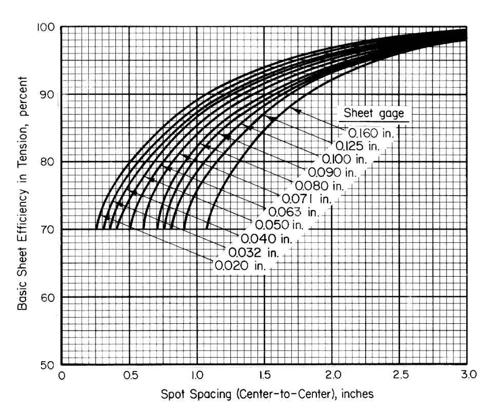
Figure 8.2.2.3.2.1. Efficiency of the parent metal in tension for spot-welded aluminum alloys.
The fatigue strength of spot-welded joints in aluminum alloy are given in Figures 8.2.2.3.2.2(a) through 8.2.2.3.2.2(e).
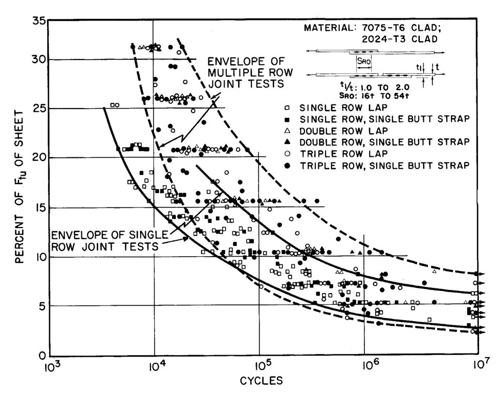
Figure 8.2.2.3.2.2(a). Fatigue strength of spot-welded joints in aluminum alloy sheet. Load Ratio = 0.05 (static failure by tearing sheet).
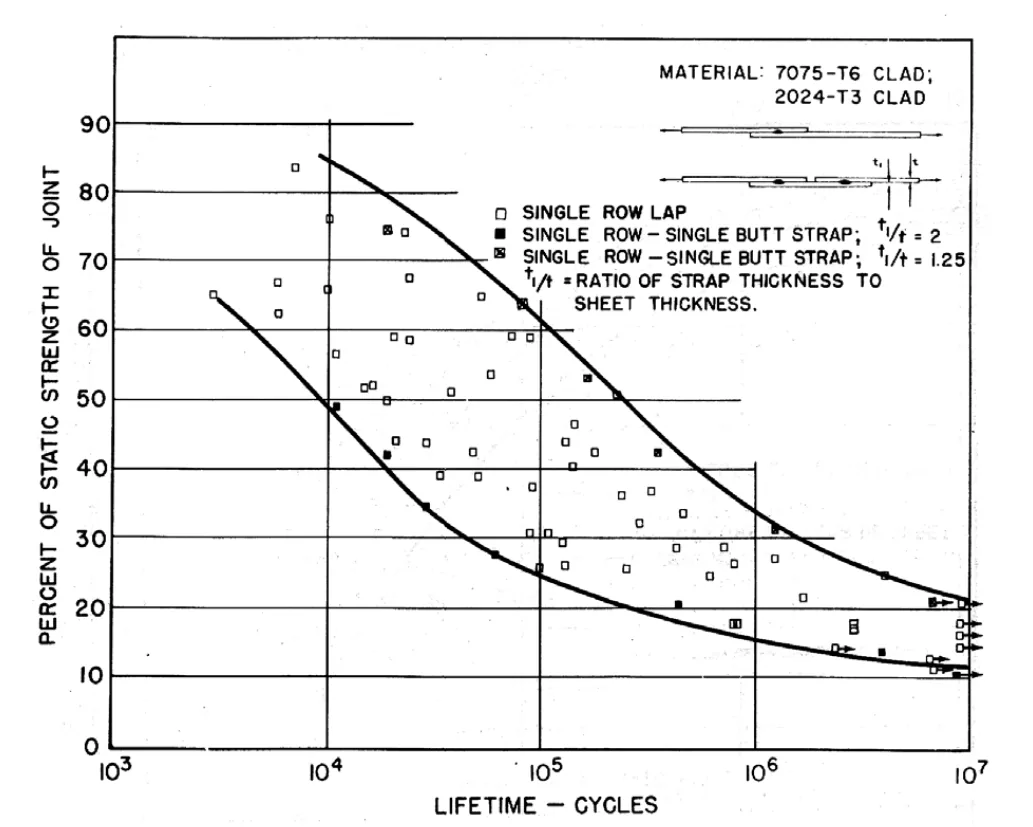
Figure 8.2.2.3.2.2(b). Fatigue strength of spot-welded joints in aluminum alloy sheet. Load Ratio = 0.05 (static failure by shear in the spot welds).
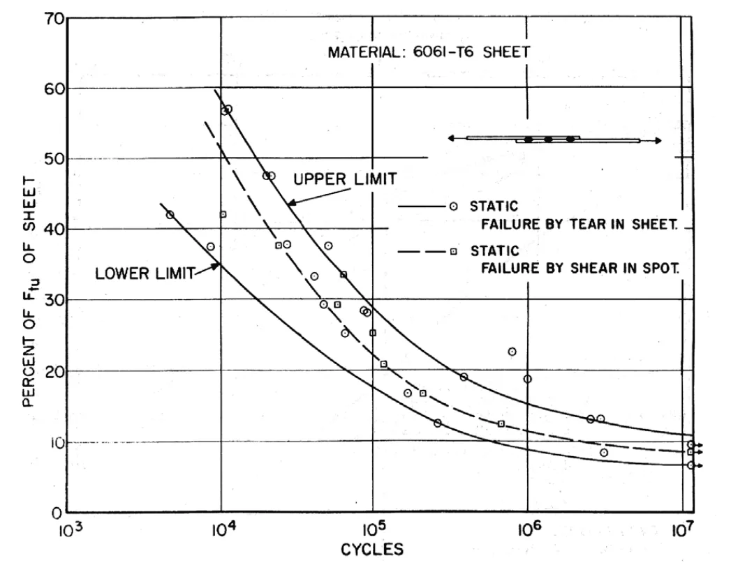
Figure 8.2.2.3.2.2(c). Fatigue strength of triple row spot-welded lap joints in 6061-T6 aluminum alloy sheet. Load Ratio = 0.05.
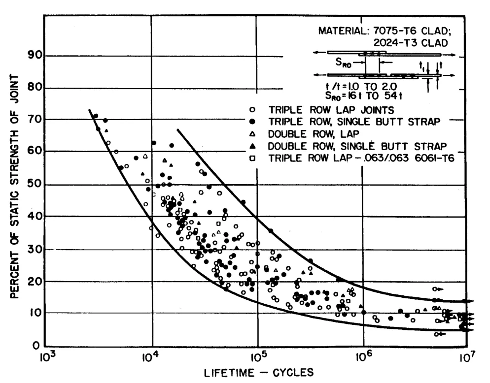
Figure 8.2.2.3.2.2(d). Fatigue strength of spot-welded multiple row joints in aluminum alloy sheet. Load Ratio = 0.05 (static failure by shear in the spot welds).
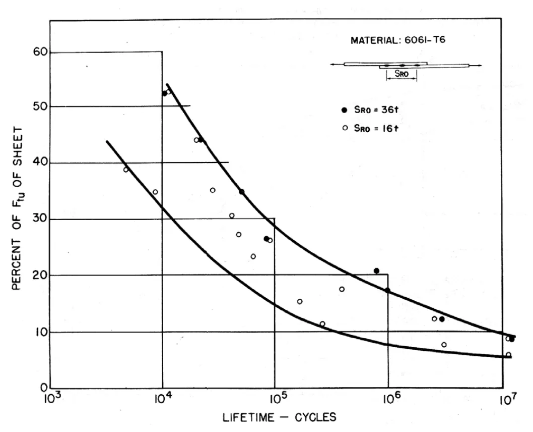
Figure 8.2.2.3.2.2(e). Fatigue strength of triple row spot-welded lap joints in 6061-T6 aluminum alloy sheet. Load Ratio = 0.05 (static failure by tear in sheets).
Design shear-strength for spot welds in magnesium alloys are given in Table 8.2.2.3.3. The thickness ratio of the thickest sheet to the thinnest outer sheet in the combination should not exceed 4:1.
| Design Shear Strength, pounds per spot | ||
|---|---|---|
| Material Ultimate Tensile Strength, ksi | Greater than 19.5 | Less than 19.5 |
| Nominal thickness of thinner sheet, in.: | ||
| 0.012 | 24 | 16 |
| 0.016 | 56 | 40 |
| 0.018 | 68 | 52 |
| 0.020 | 80 | 64 |
| 0.022 | 96 | 76 |
| 0.025 | 116 | 88 |
| 0.028 | 140 | 108 |
| 0.032 | 168 | 132 |
| 0.036 | 204 | 156 |
| 0.040 | 240 | 180 |
| 0.045 | 280 | 208 |
| 0.050 | 320 | 236 |
| 0.056 | 380 | 272 |
| 0.063 | 456 | 316 |
| 0.071 | 516 | 360 |
| 0.080 | 612 | 420 |
| 0.090 | 696 | 476 |
| 0.100 | 752 | 540 |
| 0.112 | 800 | 588 |
| 0.125 | 840 | 628 |
| a Strength based on 80 percent of minimum values specified in Specification MIL-W-6858. | ||
| b The allowable tensile strength of spot-welds is 25 percent of the design shear strength. Higher values may be used, however, if these are substantiated by tests acceptable to the procuring or certifying agency. | ||
| c Magnesium alloys AZ31B and HK31A may be spot-welded in any combination. | ||
Design shear strength for spot welds in titanium and titanium alloys are given in Tables 8.2.2.3.4(a) and (b). The thickness ratio of the thickest sheet to the thinnest outer sheet in the combination should not exceed 4:1.
where one material bends away from another. Edge distances less than those specified above may be used provided there is no expulsion of weld material or bulging of the edge of the sheet; however, these joints may have less static strength and shorter fatigue life.
d Minimum contacting overlap is twice the minimum edge distance.
e Less than minimum recommended spacing may cause shunting that leads to deterioration of weld strengths and joint life.
| Thickness of Thinnest Outer Sheet, in. | Spots/inch | Material Ultimate Tensile Strength, ksi | ||||
|---|---|---|---|---|---|---|
| Standard (Ns)d | Rangee,f | Above 185 | 150 to 185 | 90 to 149 | Below 90 | |
| Design Shear Strength, pounds per linear inch (Xm) | ||||||
| 0.001 | 40 | 1-50 | 72 | 64 | 52 | 36 |
| 0.002 | 20 | 1-30 | 144 | 128 | 104 | 72 |
| 0.003 | 12 | 1-17 | 240 | 208 | 164 | 120 |
| 0.004 | 10 | 1-14 | 324 | 280 | 228 | 152 |
| 0.005 | 9 | 1-13 | 392 | 340 | 272 | 188 |
| 0.006 | 7 | 1-10 | 432 | 380 | 304 | 220 |
| 0.007 | 6 | 1-8 | 504 | 440 | 352 | 256 |
| 0.008 | 5 | 1-7 | 552 | 488 | 392 | 284 |
| a The reduction in strength of spot-welds due to the cumulative effects of time-temperature-stress factors is not greater than the reduction in strength of the parent metal. | ||||||
| b Strength based on 80 percent of minimum values specified in Specification MIL-W-6858. | ||||||
| c The allowable tensile strength of spot-welds is 25 percent of the design shear strength. Higher values may be used, however, if these are substantiated by tests acceptable to the procuring or certifying agency. | ||||||
| d When the number of spots per inch is within 15 percent of the standard spot per inch requirement, the design shear strengths tabulated above will apply. | ||||||
| e When the number of spots differs from the standard spots per inch by 15 percent or greater, but does not exceed the noted range of spots per inch, applicable design strength will be determined as noted below: | ||||||
| Xm/Ns (K) Nr = Xr | ||||||
| where | ||||||
| Xm = design shear strength in accordance with the above table | ||||||
| Ns = standard spots per inch in accordance with the above table | ||||||
| Nr = required spots per inch (production part) | ||||||
| Xr = actual design shear strength requirement | ||||||
| K = 1.15 when number of spots per inch is reduced more than 15 percent of the standard spacing of the above table | ||||||
| K = 0.90 when number of spots is increased more than 15 percent of the standard spacing but within range of the tabular spacing. | ||||||
| f When the number of spots per inch is above the range indicated in the table, the design shear strength will remain constant at the value obtained at the top of the range. | ||||||
| Design Shear Strength, pounds per spot | ||
|---|---|---|
| Material Ultimate Tensile Strength, ksi | Above 100 | 100 and Below |
| Nominal thickness of thinner sheet, in.: | ||
| 0.010 | 164 | 128 |
| 0.012 | 220 | 160 |
| 0.016 | 320 | 236 |
| 0.018 | 392 | 272 |
| 0.020 | 424 | 312 |
| 0.022 | 488 | 360 |
| 0.025 | 580 | 424 |
| 0.028 | 684 | 508 |
| 0.032 | 836 | 620 |
| 0.036 | 1004 | 736 |
| 0.040 | 1168 | 852 |
| 0.045 | 1438 | 1028 |
| 0.050 | 1702 | 1204 |
| 0.056 | 2040 | 1416 |
| 0.063 | 2400 | 1688 |
| 0.071 | 2702 | 1914 |
| 0.080 | 3048 | 2160 |
| 0.090 | 3430 | 2435 |
| 0.100 | 3810 | 2702 |
| 0.112 | 4260 | 3030 |
| 0.125 | 4760 | 3380 |
| a The reduction in strength of spot-welds due to the cumulative effects of time-temperature-stress factors is not greater than the reduction in strength of the parent metal. | ||
| b Strength based on 80 percent of minimum value specified in Specification MIL-W-6858. | ||
| c The allowable tensile strength of spot-wells is 25 percent of the design shear strength. Higher values may be used, however, if these are substantiated by tests acceptable to the procuring or certifying agency. | ||
The allowable shear strength for copper brazing of steel alloys will be 15 ksi, for all conditions of heat treatment. Higher values may be allowed upon approval of the procuring or certifying agency.
The effect of the brazing process on the strength of the parent or base metal of steel alloys will be considered in the structural design. Where copper furnace brazing is employed, the calculated allowable strength of the base metal which is subjected to the temperatures of the brazing process will be in accordance with the following:
| Material | Allowable Strength |
|---|---|
| Heat-treated material (including normalized) used in “as-brazed” condition | Mechanical properties of normalized material |
| Heat-treated material (including normalized) reheat-treated during or after brazing | Mechanical properties corresponding to heat treatment performed |
Silver-brazed areas should not be subjected to temperatures exceeding 900°F. Silver brazing alloys are listed in specification QQ-B-654. Deviation from this specification may be allowed upon approval of the procuring or certifying agency.
The allowable shear strength for silver brazing of steel alloys will be 15 ksi, provided that clearances or gaps between parts to be brazed do not exceed 0.010 in. Deviation from this specified allowable value may be allowed upon approval of the procuring or certifying agency.
The effect of silver brazing on the strength of the parent or base metal is the same as shown for copper brazing in Section 8.2.3.1.