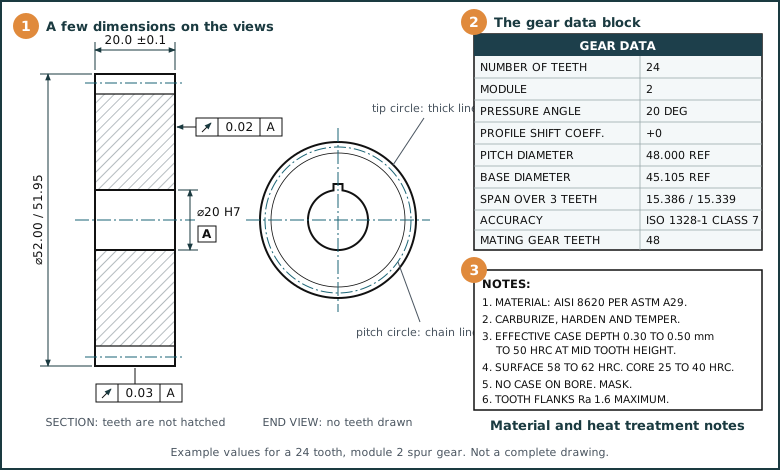
1. Dimensions on the Views
Dimension the gear blank like any turned part. The teeth are left to the data block. These are the usual callouts.
| Callout | Why it is there | Typical practice |
|---|
| Outside diameter | Sets the tooth tip. It is also the surface most shops set up and measure from. | Nominal with a minus tolerance, such as h9 to h11. Tighter if it is used as a datum. |
| Face width | Sets the load-carrying length of the tooth. | A plain tolerance, about ±0.1 mm (±0.005 in). |
| Bore or journal, as datum A | The gear runs on this axis, so the teeth must be inspected from it. | A fit class such as H7 for a bore. See the shaft and bore fit lookup. |
| Runout of the outside diameter to A | Lets the shop use the outside diameter to set up for cutting and inspection. | A circular runout tolerance, tighter for higher accuracy grades. |
| Runout of one face to A | The gear is clamped on this face for cutting. Face wobble becomes helix error. | A circular runout tolerance on the mounting face. |
| Hub, web, keyway, spline, holes | Ordinary features. | Dimension as usual. Locate a keyway to a tooth or space only if timing matters. |
| Tooth edge break | Sharp tip and end edges chip, and they are stress raisers after hardening. | A note, or a tip chamfer on the view. |
| Surface roughness | Flank finish affects pitting, scuffing and noise. | A roughness symbol on the pitch line, or a note. |
| Soft areas | Threads, thin sections and surfaces machined later must not be case hardened. | Mark the surfaces on the view and refer to them in the note. |
2. The Gear Data Block
The block has three kinds of line. Some lines define the tooth. Some are reference values that follow from the first group. Some are inspected.
| Line | Kind | What to know |
|---|
| Number of teeth | Defines | Always given. |
| Module or diametral pitch | Defines | Use the normal value for a helical gear and say so. Stay on a standard size. See the module and pitch page. |
| Pressure angle | Defines | Normal pressure angle for a helical gear. 20° is the usual choice. |
| Helix angle and hand | Defines | Helical gears only. Give the angle to enough decimals to fix the lead. |
| Tooth form | Defines | Full depth involute is standard. Name the basic rack if it is not, or give the addendum and whole depth. |
| Profile shift coefficient | Defines | Zero for a standard gear. It moves the tooth thickness and the diameters. |
| Pitch diameter | Reference | Module times teeth. It cannot be measured, so it never carries a tolerance. |
| Base diameter | Reference | The inspection machine needs it to check the involute. |
| Whole depth and root diameter | Reference | Made by the cutter. Tolerance the root diameter only when clearance is critical. |
| Tooth thickness | Inspected | Maximum and minimum. This is what sets backlash. |
| Span over k teeth | Inspected | A disc micrometer across several teeth. Quick, and it does not depend on the outside diameter. |
| Measurement over balls or pins | Inspected | Always state the ball or pin diameter. Use balls on a helical gear. |
| Accuracy grade | Inspected | The grade, the standard and the year. A bare “grade 7” means different things in different standards. |
| Mating gear and centre distance | Reference | Lets the shop and the inspector understand the mesh. Not a requirement on this part. |
Give one way of measuring tooth thickness as the requirement. A second one may be listed as an alternative. If both are requirements, they can disagree at the limits.
Leave out what you do not mean to inspect. Every toleranced line is something the supplier must measure and report. A data block with too many tolerances costs money and causes rejections that do not matter.
3. Heat Treatment Notes
A heat treatment note has to state a result that can be measured. The table shows what each process needs.
| Process | What it is | The note must state |
|---|
A typical carburizing note
CARBURIZE, HARDEN AND TEMPER PER [SPECIFICATION].
EFFECTIVE CASE DEPTH 0.40 TO 0.65 mm TO 50 HRC,
  MEASURED ON THE TOOTH FLANK AT MID TOOTH HEIGHT.
SURFACE HARDNESS 58 TO 62 HRC.
CORE HARDNESS 30 TO 42 HRC AT THE TOOTH CENTRE.
CASE DEPTH AND HARDNESS APPLY AFTER FINISH GRINDING.
NO CASE ALLOWED ON SURFACES MARKED "NO CARB".
- Effective case depth is the depth at which hardness falls to a stated value, usually 50 HRC (about 550 HV). Total case depth is deeper and harder to measure, so state which one you mean.
- Where it is measured matters. The case is thinner in the root than on the flank. State the location.
- Before or after grinding. Grinding removes case. If the depth applies to the finished tooth, say so. The heat treater then adds the grinding stock.
- A first value for case depth is 0.15 to 0.25 times the normal module. For module 2.5 that is about 0.4 to 0.65 mm. In inch units it is 0.15 to 0.25 divided by the diametral pitch. The gear rating sets the real requirement.
- Core hardness depends on the steel and the section size. Do not ask for more than the grade can reach.
- Soft areas are made by masking, by copper plating, or by leaving stock that is machined off before hardening.
A typical through hardening note
HEAT TREAT: HARDEN AND TEMPER TO 28 TO 34 HRC PER [SPECIFICATION].
CUT TEETH AFTER HEAT TREATMENT.
Keep the range at least 4 to 6 HRC points wide. A pinion is often made a little harder than its gear, because each pinion tooth sees more load cycles.
A typical nitriding note
HARDEN AND TEMPER TO 28 TO 36 HRC BEFORE FINISH MACHINING.
NITRIDE FINISHED TEETH PER [SPECIFICATION].
CASE DEPTH 0.25 TO 0.50 mm. SURFACE HARDNESS 90 HR15N MINIMUM.
WHITE LAYER 0.013 mm MAXIMUM.
A nitrided case is thin, so surface hardness is checked on a superficial scale such as HR15N. The value depends on the steel. A nitriding steel reaches about 90 HR15N. 4140 and 4340 reach about 85. The white layer is a brittle compound layer on the surface, so it carries a limit.
Notes that often follow heat treatment
- Grinding burn check. Ground, hardened teeth are etched to show overheated spots.
- Crack check. Magnetic particle inspection after the last heat treatment and grinding step.
- Shot peening. Sometimes added to the root fillets to raise bending fatigue strength. State the intensity and coverage.
- Test pieces. Case depth is measured by cutting a tooth. Allow a test coupon or a sacrificial part from each batch.
4. Common Gear Materials
Most gears use one of a small number of materials. For steel, pick the heat treatment first, because it decides the family of steel.
Steel, stainless steel, iron and bronze
| Material | Cost | Usual treatment | Surface hardness | Core hardness | Commonly quoted specifications | Where it is used |
|---|
Cost is a rough guide to the price of the bar or casting stock, from $ (cheapest) to $$$$$. It is the material only. Carburizing, grinding and vacuum melted grades add much more to the cost of a finished gear than the steel does.
Hardness values are typical ranges. Specification numbers are the ones commonly quoted for each material. Check the current revision and the product form (bar, forging or casting) before you put one on a drawing.
Stainless steel gears
Stainless steels fall into three families, and they behave very differently as gears.
- Austenitic (303, 304, 316). The best corrosion resistance. They cannot be hardened by heat treatment, so they wear and gall. Use them for light loads, and avoid running one against itself. Nitronic 60 is the austenitic grade made to resist galling.
- Martensitic (416, 420, 440C). These harden by quench and temper like alloy steel. 416 is the easy one to machine. 440C is the hardest and the most brittle. Corrosion resistance is moderate.
- Precipitation hardening (17-4 PH, 15-5 PH, 13-8 Mo). Good strength with good corrosion resistance. They are aged at a low temperature, so distortion is small. State the condition, such as H1025, on the drawing.
Call for passivation after machining on any stainless gear. Give mating stainless gears different grades or a hardness difference to reduce galling.
Plastic gears: nylon, acetal, PEEK and UHMW
Plastic gears run quietly, need little or no lubricant and do not rust. They are far less stiff and strong than steel, and they change size with temperature and moisture. The table gives typical properties of machined stock shapes.
| Material | Modulus, GPa (Msi) | Tensile strength, MPa (ksi) | Continuous use, °C (°F) | Expansion, 10−6/°C (10−6/°F) | Moisture growth, 50% RH / saturated | Comment |
|---|
These are typical data sheet values at room temperature. Grades and suppliers differ. Strength and stiffness fall quickly as a plastic warms up, so check the supplier’s curves at your running temperature.
- Cast nylon and extruded nylon are different products. Cast nylon is type 6, polymerised in the mould. It comes in large plates, rods and near-net rings with low internal stress, so it suits large gears. Extruded nylon is usually type 6/6. It comes in smaller rod and plate, and is a little stronger and stiffer.
- Filled nylons. Molybdenum disulphide adds wear resistance. Oil filled cast grades run longest without lubrication. Glass filled grades are stiffer but wear the mating gear.
- Nylon takes up water and grows. A dry nylon gear grows about 0.6 percent as it settles to normal room humidity, and about 2.5 percent in water. On a 200 mm gear, 0.6 percent is 1.2 mm on diameter. This is the main reason plastic gears jam.
- Acetal holds its size much better than nylon. Choose it for small, accurate gears.
- PEEK grades. Unfilled is the toughest. Glass filled is stiffer and more stable. Carbon filled is the strongest and stiffest. Bearing grade has the lowest friction and wear. All keep useful strength far hotter than nylon or acetal.
- UHMW polyethylene is slippery, quiet and almost immune to abrasion and moisture. It is weak and soft, it creeps, and it expands about seventeen times as much as steel. Use it for light loads and give it generous backlash.
- Mating materials. A plastic gear lasts longest against a steel or stainless pinion with a smooth flank finish. Two gears of the same plastic wear quickly. Nylon against acetal is a good all-plastic pair.
- Backlash. Plastic gears need much more backlash than steel gears. Work out the growth with the temperature and moisture section of the tooth thickness and backlash page.
What changes on the drawing of a plastic gear
- There is no heat treatment note. Ask for annealing after rough machining, so the gear does not move as internal stress relaxes.
- State the temperature at which dimensions apply. For nylon, also state the moisture condition, usually dry as machined.
- Use a wider tooth thickness tolerance than for steel. The material moves more than a tight tolerance can control.
- Ask for a full root fillet radius. Plastics are sensitive to notches.
- Do not stamp the part. Identify it by bag and tag.
- Name the exact grade and colour. “Nylon” or “PEEK” alone covers materials with very different properties.
How to choose
- Light duty, low cost: through hardened 4140 at about 30 HRC, cut after heat treatment.
- High load in a small space: carburized 8620, or 9310 for aerospace. Plan to grind the teeth.
- High accuracy with no grinding: nitride a finished gear. Distortion is very small.
- Large gears: induction harden a medium carbon steel, or use a through hardened alloy steel.
- Corrosion with real load: 17-4 PH or 15-5 PH. Use 440C for small hard gears and 416 for moderate loads.
- Corrosion with light load: 303, 304 or 316, or a plastic.
- Quiet, dry running at light load: acetal for small accurate gears, cast nylon for large ones.
- Hot, wet or chemical service in plastic: PEEK. Pick the grade for toughness, stiffness or wear.
- Wet, dirty or food service at very light load: UHMW polyethylene.
Common Mistakes
- Putting a tolerance on the pitch diameter. It cannot be measured.
- Giving an accuracy grade with no standard or year.
- Giving a measurement over pins with no pin diameter.
- Leaving out tooth thickness limits, so backlash is left to the supplier.
- Writing “case depth” with no hardness level and no location.
- Not saying whether case depth applies before or after grinding.
- Forgetting to mark threads and thin sections as soft areas.
- Leaving out the datum, so nobody knows which axis the teeth are checked from.
Standards to Open
This page gives common practice. The standards below hold the formal requirements. They are listed by number and subject only.
| Standard | Subject |
|---|
| ASME Y14.7.1 | Drawing practice and data for spur, helical and rack gears. |
| ISO 1340 | Information the purchaser gives the manufacturer for cylindrical gears. |
| ISO 2203 | How gears are shown in a view. |
| ISO 1328-1 and -2, ANSI/AGMA 2015-1 and -2 | Accuracy grades and tolerances. |
| ANSI/AGMA 2002, ISO 21771 | Tooth thickness, its measurement and gear geometry. |
| ANSI/AGMA 2004, ISO 6336-5 | Gear materials, heat treatment and material quality. |
| AMS 2759 series | Heat treatment of steel parts. Slash sheets cover carburizing and nitriding. |
| ISO 18203, SAE J423 | Measuring case depth. |
| ISO 14104, ANSI/AGMA 2007, AMS 2649 | Etch inspection for grinding burns. |
| ASTM E1444 | Magnetic particle inspection. |
| ASTM E18 | Rockwell hardness testing. |
| AMS 2759/3, AMS 2759/5 | Heat treatment of precipitation hardening and martensitic stainless steels. |
| ASTM A967, AMS 2700 | Passivation of stainless steel. |
| ASTM D5989, D6100, D6262, D4020 | Nylon, acetal and PEEK stock shapes, and UHMW polyethylene. |
| ANSI/AGMA 920, VDI 2736 | Materials for plastic gears, and plastic gear design. |
The Gear Design Guide has the full standards map and a drawing checklist that you can tick off.