Gear teeth are sized in one of two systems. Metric gears use the module m, the pitch diameter in millimetres per tooth. Inch gears use the diametral pitch DP, the number of teeth per inch of pitch diameter.
A third measure, the circular pitch p, is the distance from one tooth to the next along the pitch circle. They are all the same idea, so converting between them is a one-line calculation.
Enter any one of them with the tooth counts. The page returns the other three and the nearest standard size. It also gives the main spur gear dimensions in millimetres and inches. Add a second gear for the centre distance, ratio and contact ratio.
Module / Pitch Converter & Spur Gear Dimensions
Gear Module ↔ Diametral Pitch ↔ Circular Pitch
Tooth Size
Module is the pitch diameter in mm divided by the number of teeth. Diametral pitch is teeth per inch of pitch diameter.
Gears
Leave blank for a single gear.
Fill in to get the pitch needed for that centre distance with the teeth above. Inches when you give the size as DP or in inches, millimetres when you give it as module or in millimetres.
Tooth Size in Every Unit
Module, m (mm)
–
Diametral pitch, DP (teeth/in)
–
Circular pitch, p (mm)
–
Circular pitch, p (in)
–
Nearest standard module (mm) iPreferred ISO 54 modules, series 1. Cutters and hobs are stocked for these sizes.
–
Nearest standard diametral pitch iCommon inch diametral pitches. Module and DP sizes only match exactly at a few values.
–
Gear Dimensions
Meshing Pair
Show detailed calculation steps
The Relationships
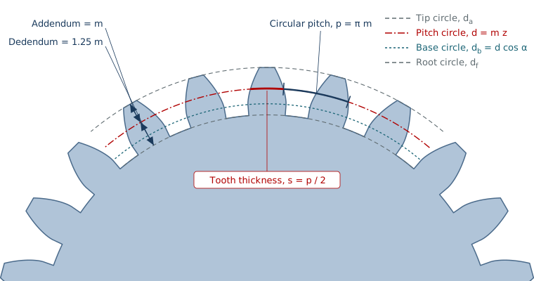
The terms on one gear. The pitch circle is the reference for size. The addendum is the tooth height above it and the dedendum is the depth below it. Circular pitch is measured along the pitch circle from one tooth to the next. The tooth takes half of it and the space takes the other half.
The three measures are tied together by two constants, π and 25.4 mm per inch:
\[ m = \frac{d}{z} = \frac{25.4}{DP} \]
\[ p = \pi m = \frac{\pi}{DP}\ (\text{in}) \]
\[ DP = \frac{z}{d_{\text{in}}} = \frac{25.4}{m} \]
A big module is a coarse tooth, and a big diametral pitch is a fine one. They run in opposite directions, so module 2 is about DP 12.7 and module 25.4 is DP 1.
Spur gear dimensions
\[ d = m z,\quad d_a = m(z+2),\quad d_f = m(z-2.5) \]
\[ d_b = d\cos\alpha,\quad a = \frac{m(z_1+z_2)}{2},\quad i = \frac{z_2}{z_1} \]
For standard full-depth teeth the addendum is m and the dedendum is 1.25 m, so the whole depth is 2.25 m. Here d is the pitch diameter and da is the outside diameter. df is the root diameter and db is the base diameter.
α is the pressure angle, a is the centre distance and i is the ratio. The tooth thickness on the pitch circle is half the circular pitch, πm/2.
Module and DP are not interchangeable in practice. A 3 mm module is 8.47 DP, which is not a standard inch pitch. Gears only mesh if they have the same module and pressure angle, so convert to find the nearest standard size, then check the nearest size actually matches.
Factor Reference Guide
Reference
Std
Standard Sizes
Preferred modules and their equivalents
Module (mm)
DP
p (mm)
p (in)
0.5
50.8
1.571
0.06184
0.8
31.75
2.513
0.09895
1
25.4
3.142
0.1237
1.25
20.32
3.927
0.1546
1.5
16.93
4.712
0.1855
2
12.7
6.283
0.2474
2.5
10.16
7.854
0.3092
3
8.467
9.425
0.3711
4
6.35
12.57
0.4947
5
5.08
15.71
0.6184
6
4.233
18.85
0.7421
8
3.175
25.13
0.9895
10
2.54
31.42
1.237
Common diametral pitches and their equivalents
DP
Module (mm)
p (mm)
p (in)
3
8.467
26.6
1.047
4
6.35
19.95
0.7854
5
5.08
15.96
0.6283
6
4.233
13.3
0.5236
8
3.175
9.975
0.3927
10
2.54
7.98
0.3142
12
2.117
6.65
0.2618
16
1.587
4.987
0.1963
20
1.27
3.99
0.1571
24
1.058
3.325
0.1309
32
0.7937
2.494
0.09817
48
0.5292
1.662
0.06545
Computed from m = 25.4 / DP and p = πm.
z min
Undercut and Contact Ratio
Fewest teeth without undercut
Standard rack\[ z_{\min} = \frac{2}{\sin^{2}\alpha} \]
Below this many teeth, a standard rack cutter digs into the root of the tooth and weakens it. It is 17.1 teeth, in practice 17, at 20° and 32 at 14.5°. Fewer teeth can be used with profile shift.
Contact ratio
The transverse contact ratio is the length of the path of contact divided by the base pitch. It is the average number of tooth pairs sharing the load. Values above about 1.2 run smoothly, and spur gears commonly reach 1.4 to 1.8.
The page computes it for standard full-depth teeth on standard centres.
Worked Example
A pair of spur gears with 10 diametral pitch, 20 and 40 teeth and a 20° pressure angle. These are the calculator’s defaults.
Module = 25.4 / 10 = 2.54 mm; p = π / 10 = 0.3142 in = 7.98 mm
d1 = 20 / 10 = 2.000 in and d2 = 40 / 10 = 4.000 in
da1 = 22 / 10 = 2.200 in and df1 = 17.5 / 10 = 1.750 in
a = (20 + 40) / (2 × 10) = 3.000 in and i = 40/20 = 2
The contact ratio is about 1.6. 10 DP is a standard diametral pitch, so standard cutters exist for it.
Notes
For what to put on the drawing, see Gear Drawing Callouts & Notes. It builds the gear data block from these dimensions.
Dimensions are for standard full-depth teeth with no profile shift and no backlash allowance. Real designs adjust for strength, backlash and manufacturing.
The undercut check and contact ratio apply to a standard rack-cut involute spur gear.
Module and diametral pitch only match exactly at a few sizes, so mixed metric and inch gears do not mesh without the same module.