From Backlash to Tooth Thickness

Backlash is the small gap between mating teeth. It stops a gear pair jamming when it heats up, sits slightly off centre, or has manufacturing errors. You get it by cutting the teeth slightly thin. It also depends on the centre distance. On a drawing you do not write “backlash”: you give the tooth thickness and its limits, and the backlash follows. This calculator takes both views.

In design mode you give the minimum backlash you want and the tolerances, and it returns how much thinner the teeth must be. In analyze mode you give thickness limits and it returns the backlash range. Either way it converts the thickness into the measurements an inspector actually takes: chordal thickness, span over teeth, and measurement over balls. It works in millimetres or inches and with module or diametral pitch.

Limits, read first.
  • External involute gears only. Spur and helical pairs. Internal gears, bevel gears and worms are not covered.
  • You supply the target and the tolerances. Recommended backlash and thickness tolerances are not built in. Take them from your gear standard, for example AGMA 2002 or the ISO and DIN equivalents.
  • Ideal teeth, no errors. It does not add allowance for tooth errors, runout, misalignment, housing deflection or thermal growth. Put those in your target minimum backlash.
  • Chordal thickness and measurement over balls are for spur gears. Helical gears get the span measurement only, which needs enough face width.
  • Thickness is at the reference circle, in the normal plane, as in the usual drawing data table.
Tooth Thickness and Backlash
Tooth Thickness ↔ Backlash, in mm or inches
Units & Gear Pair
Changing the units converts the lengths you have entered.
Normal (not transverse) for helical gears.
0 for spur gears.
Centre Distance & Measurement (optional)
Blank means the zero-backlash centre for the shifts above. Enter your housing centre distance to see what the gears do in it.
Blank means a full tip, used for the chordal addendum.
Blank uses a ball that touches the flanks on the pitch circle.
For the span check on helical gears.
What do you want to find?
Design mode returns the thickness limits to put on the drawing. Analyze mode checks limits you already have.
The smallest play the mesh may have. Take the value from your standard or experience.
The width of the thickness band, set by the process and the accuracy grade.
The housing tolerance either way.
Temperature & Moisture Growth (optional, for plastic gears)
Above the temperature at which the parts were measured. Negative for cold running.
The housing usually runs cooler than the gears.
Nylon grows as it takes up water. Dimensions are taken as dry.
Leave the temperature rises at 0 and the moisture as dry to skip this. In design mode the thickness allowance is then set so the minimum backlash still holds after growth.
Backlash and Operating Mesh
Thickness Limits to Specify and Inspect
“At maximum thickness” is the tooth at its upper deviation, with the most metal. “At minimum” is the tooth at its lower deviation. Use whichever of the thickness, span or over-ball measurement your inspector will use. Values are shown in both units.
Show detailed calculation steps
How It Works
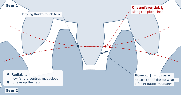
Close view of one tooth of gear 1 in a space of gear 2. The left flanks touch. The gap at the right flanks is marked three ways: circumferential backlash along the pitch circle, normal backlash square to the flanks, and radial backlash as the centre distance change that would close the gap.
Where backlash is measured. One pair of flanks drives and the other pair has a gap. The same gap has three common measures. Circumferential backlash jt runs along the pitch circle. Normal backlash jn is square to the flanks and is what a feeler gauge reads. Radial backlash jr is how far the centres would have to close to remove the gap.

A tooth that is nominally half a pitch thick is cut thinner by an allowance. Two thinner teeth in the same space leave a gap. For a pair at centre distance a′ the gap measured on the working circles is the circumferential backlash:

\[ j_{wt} = p_w - t_{w1} - t_{w2} \] \[ t_{wi} = r_{wi}\left[\frac{2 s_{ti}}{m_t z_i} + 2\left(\operatorname{inv}\alpha_t - \operatorname{inv}\alpha'_{wt}\right)\right] \] \[ j_n = j_{wt}\cos\alpha'_{wt}\cos\beta_b \]

Here st is the tooth thickness in the transverse plane and rw is the working radius. pw is the pitch on the working circle. α′wt is the working pressure angle, which the centre distance sets. βb is the base helix angle. tw is each tooth’s thickness on its working circle. The function inv is the involute function, inv θ = tan θ − θ. The normal backlash jn is the gap a feeler gauge would measure between the flanks, and is the number most standards and drawings use.

The two simple rules

\[ \Delta j_n \approx -\left(\Delta s_{n1} + \Delta s_{n2}\right)\quad(\text{thinner teeth}) \] \[ \Delta j_n \approx 2\,\Delta a\,\sin\alpha_n\quad(\text{wider centres}) \]

Δsn is a change in normal tooth thickness and Δa is a change in centre distance. Thinning both teeth by 0.05 each opens about 0.1 of normal backlash. Opening the centres by 0.05 opens about 0.034 at 20°. The calculator uses the exact expressions, and these rules are the check that the answer is sensible.

From thickness to measurements

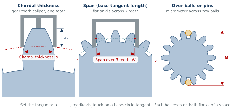
Tooth thickness on the pitch circle cannot be measured directly. An inspector checks it one of three ways:

Three panels. Chordal thickness: a gear tooth caliper with its tongue on the tooth tip and its jaws on the flanks. Span: flat anvils across three teeth, touching along a tangent to the base circle. Over balls: a ball in each of two opposite tooth spaces with the measurement taken across them.
Three ways to check tooth thickness. A gear tooth caliper reads the chordal thickness sc at a set depth ac below the tip. A disc micrometer reads the span Wk across k teeth. A micrometer over two balls or pins reads M. Thinner teeth give a smaller reading in all three.
\[ W_k = m_n\cos\alpha_n\left[\left(k-\tfrac12\right)\pi + z'\operatorname{inv}\alpha_n\right] + 2x\,m_n\sin\alpha_n \] \[ \Delta W = \Delta s_n\cos\alpha_n \] \[ s_c = d\sin\frac{s}{d},\qquad a_c = h_a + \frac d2\left(1-\cos\frac sd\right) \]

Here x is the profile shift coefficient. z′ is the tooth count, or the equivalent count for a helical gear. s is the thickness on the pitch circle of diameter d, and ha is the addendum.

The span Wk is the distance across k teeth between two parallel jaws. A change in thickness moves the span by that change times the cosine of the pressure angle. The chordal thickness sc and chordal addendum ac are what a gear tooth caliper reads. The measurement over balls uses the same maths as the ball-measurement calculator, with the thickness change treated as an equivalent profile shift.

Factor Reference Guide
Reference
j

The Four Kinds of Backlash

KindWhat it is
Normal, jnThe gap between the flanks, measured perpendicular to the tooth surface. The usual drawing value.
Circumferential, jwtThe gap along the working pitch circle. Also called transverse or tangential backlash.
Radial, jrHow far the centre distance must close to bring the flanks into contact. jr = jwt / (2 tanα′wt).
AngularHow far one gear turns with the other held. Shown in arc-minutes for gear 1.

For a spur gear jn = jwt cosα′. For a helical gear the base helix angle comes in too. A mesh has a minimum backlash, with the thickest teeth at the closest centres. It also has a maximum, with the thinnest teeth at the widest centres. Both matter. The minimum keeps the teeth from jamming. The maximum limits play and impact.

M

Which Measurement to Specify

  • Chordal thickness with a gear tooth caliper. Quick and portable, but it depends on the outside diameter being right, and it is less precise.
  • Span (base tangent) over k teeth with a disc micrometer. Independent of the outside diameter and of runout of the blank. The best choice where the face width allows it, including for helical gears.
  • Measurement over balls or pins. Accurate and common for fine pitches and for internal gears. It sees the effect of runout, so use it with a runout check.

Drawings give the limits of whichever method the manufacturer and inspector agree on, and sometimes more than one. The table shows all three at the maximum and minimum thickness so they are consistent.

Std

Where the Values Come From

This tool does the geometry. It does not choose your backlash or your thickness tolerance. Those come from:

  • Tooth thickness and backlash: AGMA 2002 (tooth thickness specification and measurement) and, for the ISO route, ISO 21771 and its related standards.
  • Thickness tolerance: in practice set by the accuracy grade and the manufacturing process. See the Gear Design Guide for the accuracy standards (ISO 1328, AGMA 2015).
  • Centre distance tolerance: from the housing design and the gear accuracy grade. ISO/TR 10064 gives guidance.
Check the current edition of each standard before using a value on a drawing.
JS

Using the Maths on Another Page

The calculation is in js/gear-thickness-math.js, which depends only on js/gear-measure-math.js. Both work in the browser and in Node and know nothing about this page.

var g = GearThickness.pairGeometry({ mn: 2.5, z1: 24, z2: 60, alphaN: 20, beta: 0, x1: 0, x2: 0 });
var d = GearThickness.designAllowance(g, g.a0, 0.10, 0.025, 0.04, 0.05);
d.u               // upper thickness deviation, each gear
d.range.min.jn    // minimum normal backlash
GearThickness.span(2.5, 24, 20, 0, 0, 3)   // span over 3 teeth

The page script, js/gear-thickness.js, reads the form and fills the results. It converts units at the edge, so the maths always works in one unit.

Worked Example

A pair with 10 diametral pitch, 24 and 60 teeth, 20° and no shift. The housing centre distance is the zero-backlash value, 4.200 in ±0.001. Tooth thickness tolerances are 0.0015 and 0.0020 in. The minimum normal backlash wanted is 0.004 in. These are the defaults, in design mode.

  • Nominal normal thickness sn = π / (2 × 10) = 0.15708 in for both gears
  • Upper deviation needed on each gear = −0.00249 in, with the centres closed to 4.199. Lower deviations −0.00399 (gear 1) and −0.00449 (gear 2)
  • Gear 1 normal thickness therefore 0.15459 at most and 0.15309 at least
  • Normal backlash 0.0040 to 0.0087 in (0.102 to 0.220 mm)
  • Circumferential backlash 0.0043 to 0.0092 in
  • Radial backlash 0.0059 to 0.0126 in
  • Angular backlash 12.2 to 26.4 arc-minutes at gear 1

The gear 1 inspector can check that thickness range three ways:

  • Chordal thickness 0.15448 to 0.15298 in (nominal 0.15697)
  • Span over 3 teeth 0.76930 to 0.76789 in (nominal 0.77165)
  • Over 0.1715 in balls 2.6296 to 2.6260 in (nominal 2.6354)

Switch the units to millimetres and the same gear is described in millimetres.

Temperature and Moisture Growth

Backlash is set at room temperature on dry parts. In service the gears warm up, and a nylon gear also takes up water. If the gears grow more than the housing, the backlash closes.

A gear that grows keeps its shape. On the mesh, a gear that grows by a strain ε acts like a centre distance that is shorter by its working radius times ε. The housing growth lengthens the centre distance. The page finds the centre distance that gives the same backlash:

\[ a_{\text{eff}} = a\,(1+\varepsilon_h) - r_{w1}\,\varepsilon_1 - r_{w2}\,\varepsilon_2 \] \[ \varepsilon = \alpha\,\Delta T + \text{moisture growth} \]

Here α is the thermal expansion coefficient and ΔT is the temperature rise. rw1 and rw2 are the working pitch radii, and the subscript h is the housing. The backlash is then worked out again at aeff. If everything grows by the same amount, aeff equals a and nothing changes.

Steel gears in a steel housing barely move. Plastic gears move a lot. The table shows why.

MaterialExpansion, 10−6/°CGrowth for a 40 °C riseMoisture growth, dry to 50% RHMoisture growth, saturated

The values are typical of data sheets for machined stock. Cast nylon is type 6 and extruded nylon is usually type 6/6. The PEEK grades differ mainly in stiffness and expansion. See Gear Drawing Callouts & Notes for strength, temperature limits and how to choose.

Plastic gears need far more backlash than steel gears. A dry nylon gear of 100 mm pitch diameter grows about 0.6 mm as it settles to room humidity, and another 0.35 mm for a 40 °C rise. Choose the worst condition the gear will see and design the minimum backlash there.
Notes
  • To turn these limits into a gear data block and drawing notes, see Gear Drawing Callouts & Notes.
  • All maths uses the exact working-circle relations, not the small-angle rules. The rules in the explanation are the cross-check.
  • The minimum and maximum backlash are the worst cases of the tolerances stacked together. A real mesh usually lands between them.
  • Thermal and moisture growth is treated as a uniform change of size. A gear that is hotter at the teeth than at the hub, or wet only at the surface, grows unevenly.
  • Plastic properties are typical data sheet values. Use the supplier’s figures for the exact grade.
  • Backlash that is right at room temperature can close when the gears run hot. Light alloys and mixed steel and aluminium housings are the worst cases. Allow for it in the minimum.

Cite This Work