The Smallest Solid Shaft That Carries the Load

A gear shaft sees torque from the power it carries and bending from the gear forces. The bending is turned into a fully reversed stress by the rotation, while the torque is usually steady. Keyways, shoulders and grooves multiply the stress locally. This page finds the smallest solid round shaft that meets a design factor. It uses the distortion-energy fatigue criteria of standard machine design: Goodman, Gerber, Soderberg and ASME elliptic. It adds a static yield check. It also runs the other way: give a diameter and get the factor of safety.

Use it for a first size before you choose bearings and fits. The result is a minimum, so round up to a standard size. Then check deflection, critical speed, and the bearing and gear ratings.

Limits, read first.
  • Solid round steel shaft, one section. It sizes the shaft at the one critical section where you give the loads and the stress concentration. A real shaft needs this at every shoulder, keyway and bearing seat.
  • Strength only. It does not check deflection, slope at gears and bearings, torsional stiffness or critical speed. Those often set the size of a gear shaft before strength does.
  • Bending is treated as fully reversed (a fixed load on a rotating shaft). Enter a mean bending moment separately if there is one. Axial load and shear from transverse force are not included.
  • Stress concentration factors are your input. The presets are rough first-pass values for steel. Use the real values for your keyway, fillet or groove once the geometry is set.
  • The endurance limit is an estimate from the tensile strength and the Marin factors, with a scatter of 10 to 20 percent. Use test data when you have it and a design factor to match the risk.
  • Material strengths are typical values. Use the certified strength of the bar you will buy. Steels above 1400 MPa and non-steel shafts are outside what the estimate covers.
  • Stainless steels are included. The 300 series, 416 and 17-4 PH are in the material list. The endurance limit estimate was built on carbon and alloy steel data, so treat it as approximate for stainless, and allow for corrosion fatigue in a wet environment. Plastic shafts are not covered.
Shaft Size
Minimum Diameter for Bending and Torque
What to Find
Changing the units converts the values you have entered.
Torque
Torque fluctuation about the steady value (peak minus mean). Zero for a steady load.
Bending
The moment is for a straight spur gear on a simply supported shaft, from tangential and radial force. Helical gears add axial force and moment, which is not included.
Only if the bending direction does not rotate with the shaft. Usually zero.
Material and Surface
Typical values for carbon steel bars, and specification minimums for the stainless grades. Choose “Enter my own” to type the strengths of your bar.
50 gives no reduction. 99 is common for important shafts.
1 for no other correction. Use less than 1 for corrosion or plating.
Stress Concentration and Design Factor
Picking one fills Kt and Kts with first-pass values. Overwrite them once you have real geometry.
Leave blank to apply the full Kt (q = 1). A radius lets the notch sensitivity reduce it.
1.5 to 2 for well known loads and good data, higher where the loads or the material are uncertain.
Result
The Four Fatigue Criteria Compared
The selected criterion is highlighted. The spread between them is a measure of how much the choice of mean-stress rule matters for this load.
Show detailed calculation steps
How It Works

Bending and torque combine into one equivalent stress by the von Mises (distortion energy) rule. This is done twice: once for the alternating part and once for the steady part. Each part carries its own stress concentration:

\[ A = \sqrt{4\,(K_f M_a)^2 + 3\,(K_{fs} T_a)^2} \] \[ B = \sqrt{4\,(K_f M_m)^2 + 3\,(K_{fs} T_m)^2} \] \[ d = \left\{ \frac{16\,n}{\pi}\left[\frac{A}{S_e} + \frac{B}{S_{ut}}\right]\right\}^{1/3}\quad\text{(DE-Goodman)} \]

M is the bending moment and T is the torque. The subscript a marks the alternating part and m marks the steady (mean) part. Kf and Kfs are the fatigue stress concentration factors in bending and in torsion. A is the load that cycles and B is the load that stays. A is divided by the endurance limit Se. B is divided by the tensile strength Sut. That shows how much of each the shaft can take. The design factor n scales the answer. The other criteria change only how the steady stress and the alternating stress trade off.

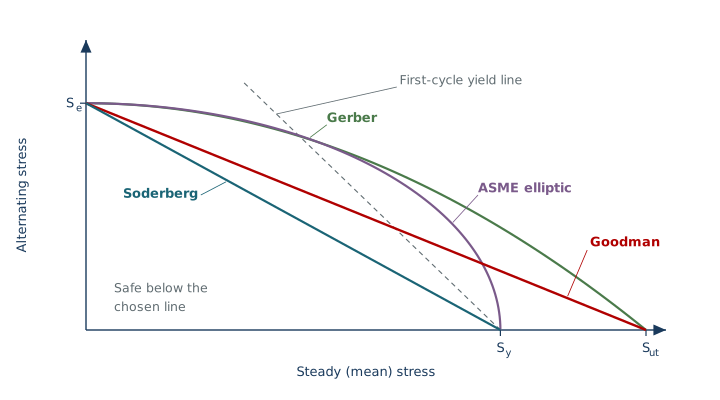
Each criterion draws a different boundary between safe and unsafe combinations of steady and alternating stress:

Graph of alternating stress against steady stress. All four criteria start at the endurance limit Se on the vertical axis. The Goodman line and the Gerber parabola end at the tensile strength Sut on the horizontal axis. The Soderberg line and the ASME ellipse end at the yield strength Sy. A dashed line marks first-cycle yield.
The four criteria. A point below a line is safe by that criterion. Soderberg is the most cautious and Gerber the least. Goodman and Gerber end at the tensile strength, so they can pass a load that yields on the first cycle. That is why the page adds a separate yield check.

The endurance limit

\[ S_e = k_a k_b k_c k_d k_e k_f\, S'_e,\qquad S'_e = 0.5\,S_{ut}\ (\le 700\ \text{MPa}) \]

The test-bar limit S′e is reduced for surface finish (ka), size (kb), temperature (kd) and reliability (ke). The size factor depends on the answer, so the calculation iterates. The loading factor kc is 1 because torsion is already handled by the von Mises combination.

Stress concentration

\[ K_f = 1 + q\,(K_t - 1),\qquad q = \frac{1}{1 + \sqrt{a}/\sqrt{r}} \]

A notch weakens a part in fatigue less than its theoretical factor Kt suggests, because a small, sharp notch only affects a thin skin. The notch sensitivity q runs from 0 (no effect) to 1 (full effect). It depends on the notch radius r and on the Neuber constant √a, which falls as the steel gets stronger.

Reference Guide
Reference
DE

Which Fatigue Criterion

CriterionUse
GoodmanStraight-line rule. Safe and widely used for a first size.
GerberFits ductile test data best. Gives the smallest shaft.
ASME ellipticFits the data about as well and protects against yield.
SoderbergUses yield strength for the steady part. The most conservative.

On a typical gear shaft the bending is reversed and the torque is steady. The torque term then dominates B, and the criteria differ by only a few percent. They spread more when the steady stress is large.

Kt

First-Pass Stress Concentration Values

FeatureKt bendingKts torsion
Shoulder, well rounded1.71.5
Shoulder, sharp2.72.2
End-milled keyseat2.143.0
Retaining ring groove5.03.0

These are the rough numbers used to get a first diameter before the geometry is fixed. Once you know the fillet radius and the diameter ratio, take Kt from the published charts for the actual shape. Enter it with the radius.

A keyway and a press-fitted gear both concentrate stress. Use the larger of the factors that apply at the section.

Next

After You Have a Diameter

  • Round up to a standard size, and check that the shaft is not so small it cannot carry the gear bore, the keyway or the bearing seat.
  • Check stiffness: deflection and slope at the gear mesh and at the bearings. Gear shafts are often sized by stiffness, not strength.
  • Check critical speed and torsional natural frequency if the speed is high.
  • Choose the fits for the gear bore and the bearing seats with the Shaft & Bore Fit Lookup.
  • Check the shaft reliability in service with the NSWC-11 shaft failure rate model.
Src

Where the Method Comes From

  • Fatigue criteria and Marin factors: Budynas and Nisbett, Shigley’s Mechanical Engineering Design, chapters on fatigue failure and on shafts and shaft components. The same relations appear in other machine design texts.
  • Notch sensitivity (Neuber constant): the same text, from the Neuber relation with curve fits for steel.
  • Stress concentration factors: Peterson’s Stress Concentration Factors.
  • Shaft design practice: ASME B106.1M (design of transmission shafting) was withdrawn but is still widely cited. Check your customer’s or your own design standard for a required method.
The distortion-energy criteria here are for ductile steel. Check the current edition of the text and any required design standard before using a result on a drawing.
JS

Using the Maths on Another Page

The calculation is in js/shaft-size-math.js. It works in the browser and in Node, knows nothing about this page, and uses N, mm and MPa throughout.

var kf = ShaftSize.fatigueConcentration(2.14, 1.5, 630, 'b').Kf;
var r = ShaftSize.minDiameter({
  criterion: 'goodman', Sut: 630, Sy: 530, finish: 'machined',
  tempF: 70, reliability: 90, kOther: 1, Kf: kf, Kfs: 2.6,
  Ma: 120000, Mm: 0, Tm: 95500, Ta: 0, n: 2     // N mm
});
r.d, r.dFatigue, r.dStatic, r.Se.Se

The page script, js/shaft-size.js, reads the form, converts units and draws the results.

Notes
  • The size factor kb uses the rotating-beam expressions, with d in millimetres. It is 1.24 d−0.107 from 2.79 to 51 mm, and 1.51 d−0.157 above that to 254 mm.
  • The surface factor is ka = a Sutb, with Sut in MPa. The coefficients a and b depend on the finish: ground, machined or cold drawn, hot rolled, or as-forged.
  • Reliability is tabulated at 50, 90, 95, 99, 99.9, 99.99 and 99.999 percent. Values between those points are interpolated on the unreliability.
  • The standard size shown is the next larger one. In millimetres it comes from the R20 series. In inches it steps by sixteenths to 2 in, eighths to 6 in, and quarters above that.

Cite This Work