How Many Teeth Share the Load?

The contact ratio is the average number of tooth pairs sharing the load. At 1.0 exactly one pair is in contact at every instant and the next pair arrives just as the last leaves. Above 1 two pairs overlap for part of the mesh. Higher means smoother, quieter running and less load on each tooth. That makes it one of the first checks on any gear pair.

This calculator finds the transverse contact ratio of external and internal pairs and of a pinion with a rack. For helical gears it adds the axial and total contact ratio. It accounts for profile shift, centre distance and measured outside diameters, and it flags interference. The maths is in a stand-alone script, js/gear-contact-math.js, that other pages can load and call.

Limits, read first.
  • Involute gears only. External and internal spur and helical pairs and a rack. Bevel gears, worms, cycloidal and non-involute teeth are not covered.
  • Theoretical, unloaded contact ratio. It uses ideal tooth shapes. Real contact depends on tooth errors, deflection under load, tip and root relief and backlash, so the working value is a little different.
  • Full tips unless you say otherwise. Tip radius is the standard r + (ha + x) m. A shifted gear with shortened tips needs its measured outside diameter entered.
  • Interference is checked, not designed out. It flags tips that reach past the tangent point, but does not check undercut, fillet trochoid or tip-root clearance in full.
  • Internal pairs use a stated shift convention and do not check ring-gear interference such as trimming or fillet contact.
  • Helical gears use the transverse plane and a simple axial ratio. They do not model crowning, partial face contact or the gear housing.
Contact Ratio of a Gear Pair
Contact Ratio: εα, εβ and εγ
Type of Mesh & Teeth
Tooth Form
The contact ratio does not depend on size. Face width, centre distance and outside diameters are in inches with a diametral pitch and in millimetres with a module.
0 for spur gears.
For the axial contact ratio of helical gears.
Tip height in modules. 1.0 is full depth, 0.8 stub.
Profile Shift & Centre Distance (optional)
Blank means zero backlash for the shifts above. Enter a value to see the effect of a changed centre distance.
Blank means a full tip. Enter a measured value for shortened tips.
Contact Ratio
Contact Ratio vs Teeth

The curve holds your other settings and changes only the mating tooth count. The red dot is your gear. The ratio rises toward the rack limit of about 1.98 as the mating gear gets larger.

Helix Angle

The blue curve is the total contact ratio at your face width and the red curve is the transverse part. The gap between them is the axial contact ratio. Enter a face width to see helical gears gain.

Show detailed calculation steps
How It Is Calculated

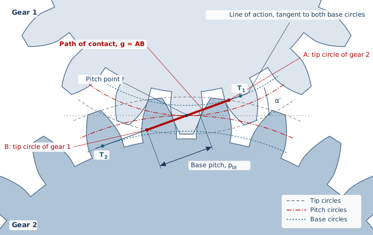
Involute teeth touch along one straight line, the line of action. It is tangent to both base circles and passes through the pitch point. Contact can only happen where both teeth exist, so it is limited to the part of the line inside both tip circles.

Two meshing spur gears with their tip, pitch and base circles. The line of action is tangent to both base circles at T1 and T2. The path of contact is the part of that line between A and B, where the two tip circles cross it. The base pitch is marked along the line.
The path of contact. Contact runs from B to A, where the two tip circles cut the line of action. Its length is g. Teeth follow each other along the line one base pitch apart. Here g is longer than one base pitch, so a second pair is in contact for part of the mesh. The contact ratio is g divided by the base pitch.
\[ \varepsilon_\alpha = \frac{g}{p_{bt}},\qquad p_{bt} = \pi\, m_t \cos\alpha_t \] \[ m_t = \frac{m_n}{\cos\beta},\quad \alpha_t = \arctan\frac{\tan\alpha_n}{\cos\beta} \] \[ g = \sqrt{r_{a1}^2 - r_{b1}^2} + \sqrt{r_{a2}^2 - r_{b2}^2} - a'\sin\alpha' \quad(\text{external pair}) \] \[ \varepsilon_\beta = \frac{b \sin\beta}{\pi\, m_n},\qquad \varepsilon_\gamma = \varepsilon_\alpha + \varepsilon_\beta \]

The path of contact g is the length of the line of action over which one pair of teeth touches. It starts where the tip of one gear enters the mesh. It ends where the tip of the other gear leaves. The base pitch pbt is the spacing between successive teeth along that same line. The contact ratio is how many tooth spacings fit in the path. ra is the tip radius and rb is the base radius. a′ is the operating centre distance and α′ is the operating pressure angle.

mt and αt are the module and pressure angle in the transverse plane. For a spur gear they equal mn and αn. β is the helix angle and b is the face width. εβ is the axial contact ratio, which only helical gears have. εγ is the total.

Internal gears and racks

\[ g_{\text{internal}} = \sqrt{r_{a1}^2 - r_{b1}^2} - \sqrt{r_{a2}^2 - r_{b2}^2} + a'\sin\alpha' \] \[ g_{\text{rack}} = \sqrt{r_{a1}^2 - r_{b1}^2} - r_1\sin\alpha_t + \frac{(h_a - x_1)\,m_n}{\sin\alpha_t} \]

In an internal pair the ring gear’s tip is inside its pitch circle, so its term is subtracted. A rack is a gear of infinite radius, so its tooth side is a straight line. In the rack formula ha is the addendum coefficient and x1 is the pinion’s profile shift.

Profile shift and centre distance

\[ \operatorname{inv}\alpha' = \operatorname{inv}\alpha_t + \frac{2\tan\alpha_n\,(x_1 + x_2)}{z_1 + z_2} \] \[ a' = a\,\frac{\cos\alpha_t}{\cos\alpha'},\qquad \operatorname{inv}\theta = \tan\theta - \theta \]

x1 and x2 are the profile shift coefficients. z1 and z2 are the tooth counts. a is the standard centre distance. With zero backlash a positive total shift opens the centre distance and the operating pressure angle. The contact ratio then drops. A larger centre distance does the same. The page lets you see both.

Factor Reference Guide
Reference
Targets

What Contact Ratio Is Good Enough

Transverse contact ratioWhat it means
below 1.0Gap in the mesh: not continuous. Not acceptable.
1.0 to 1.2Low. Noisy, and very sensitive to errors.
1.2 to 1.4Acceptable for light duty.
1.4 to 1.8Good. Typical standard spur gears.
1.8 and aboveVery good: high contact ratio gearing, internal pairs and racks.
Common guidance, not a standard. Standard 20° spur pairs range from about 1.4 to just under 2.

Standard 20° full-depth gears run at about 1.6 for a 20 and 40 tooth pair and approach 1.98 against a rack. Fewer teeth, larger pressure angles, shorter teeth and a wider centre distance all lower it. Internal gears are higher because the ring tooth wraps the pinion tooth.

While the ratio is between 1 and 2, the load alternates. For part of each base pitch two pairs carry it. For the rest, one pair does. The single-pair zone is where one tooth carries the whole load and bending stress peaks.

εβ

Helical Gears and the Axial Ratio

A helical tooth enters the mesh gradually along its width, so the load builds up and fades instead of arriving all at once. The axial contact ratio measures this: the face width times the sine of the helix angle, divided by the normal circular pitch. The total contact ratio is the transverse and axial parts added together.

A whole-number axial ratio keeps the total length of the contact lines nearly constant, which gives the smoothest load carrying. The page shows the face width for that in the math script (faceWidthForAxial).

For helical gears the page calculates everything in the transverse plane. The transverse module is mn/cosβ. The transverse pressure angle is larger than the normal one. So a helical pair has a slightly lower transverse ratio than the same spur pair. The axial ratio more than makes up for it once the face width exceeds a few modules.

JS

Using the Maths on Another Page

All the calculation is in js/gear-contact-math.js. It has no dependency on this page and works in the browser (window.GearContact) or in Node (require).

var r = GearContact.contactRatio({ z1: 20, z2: 40, mn: 2 });
r.epsAlpha   // 1.635
r.epsGamma   // total, with beta and b set
GearContact.rackLimit(20)   // 1.981
GearContact.seriesVsTeeth(base, [20, 40, 80])

The page script, js/gear-contact.js, only reads the form, calls this module and fills the results. The shared js/nswc-ui-common.js holds number formatting and the chart helpers.

Worked Example

A spur pair with 10 diametral pitch (module 2.54) and 20 and 40 teeth at 20°. These are the defaults. Lengths are in inches.

  • r1 = 1.000, r2 = 2.000, rb1 = 0.9397, rb2 = 1.8794, ra1 = 1.100, ra2 = 2.100, a′ = 3.000
  • g = √(1.1² − 0.9397²) + √(2.1² − 1.8794²) − 3 sin 20° = 0.5718 + 0.9370 − 1.0261 = 0.4827 in
  • pbt = π × 0.1 × cos 20° = 0.2952 in

εα = 0.4827 / 0.2952 = 1.635. Two pairs share the load for 63.5 % of the mesh and one pair for 36.5 %.

Set the helix angle to 15° and the face width to 1 in. The transverse ratio becomes 1.561, the axial ratio 0.824 and the total 2.385. Set the type to pinion and rack and it rises to 1.769. Set 12 teeth on the pinion and 60 on the gear and the page flags interference.

Notes
  • Contact ratio is a design check and does not go on the drawing. For what does, see Gear Drawing Callouts & Notes.
  • Contact ratios are theoretical values for ideal involute teeth with no backlash and no deflection. Treat 1.2 as a minimum for continuous running and 1.4 or more as comfortable.
  • The result does not depend on the module. Only the tooth counts, pressure angle, addendum, shift and centre distance matter. Lengths just need to be in inches with a diametral pitch and in millimetres with a module.
  • This checks one thing about a gear pair. It is not a strength, wear or noise rating.

Cite This Work