Identify a Spur Gear From Ball Measurements

An unknown spur gear is easy to count and measure but hard to identify. The tooth size and pressure angle are not visible, and a gear cut with profile shift looks like a different gear. The trick is to measure over balls: two balls (or pins) seated in tooth spaces on opposite sides, and the distance across them. That number depends on the module, the pressure angle and how much the teeth are shifted.

Enter the tooth count, the outside diameter, the ball size and the measurement over balls. Add the root diameter and a second ball size if you have them. The page tests every standard module and diametral pitch at 14.5°, 20° and 25°, and ranks them by how well they agree. It then reports the pitch and base diameters, profile shift, tooth thickness and the ball sizes to use.

Limits, read first.
  • External spur gears only. Helical gears, internal gears, bevel gears and worms need different formulas.
  • Standard sizes only. It searches ISO preferred modules and common diametral pitches at 14.5°, 20° and 25°. A non-standard module or angle will show as a poor fit.
  • Standard tooth proportions. It assumes a 1.25 m dedendum and no tip shortening. Topped or special-tool gears will show a small disagreement in the outside or root diameter.
  • The pressure angle can hide. For some ball sizes 14.5°, 20° and 25° all fit. Add a second ball of a different size when the table shows more than one fit.
  • Garbage in, confident answer out. A wrong tooth count or a ball that does not seat on the flanks gives a plausible but wrong result. Count twice and check the warnings.
Over-Ball Gear Identifier
Measurement Over Balls → Module, Pressure Angle, Profile Shift
Units & What You Know
Enter every length in inches.
Your Measurements
Count them. This must be right.
Measure across the tips with calipers or a micrometer. For an odd tooth count measure at a tip and across the nearest opposite tip.
The ball (or pin) you actually used. Measure it too.
Two balls seated in tooth spaces as nearly opposite as possible, measured over the outside of the balls.
Blank to skip. Measure with a point micrometer or a ball in the root, then subtract.
Second Ball (optional, pins down the pressure angle)
A noticeably different size, such as twice the first.
In the same units. Candidates within three times this are called a fit.
Best Match
Candidates, Best First
Each row assumes that size and pressure angle and works out the profile shift x from each measurement. When the x values agree, that combination fits. The disagreement column is the spread in x times the module.
Show detailed calculation steps
How the Measurement Works
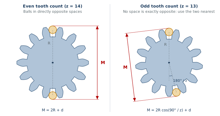
Two gears with a ball seated in two tooth spaces and the measurement M taken across the outsides of the balls. With an even tooth count the balls are directly opposite. With an odd tooth count they sit in the two spaces nearest to opposite, half a tooth pitch off the centre line.
Measurement over balls, M. R is the distance from the gear centre to a ball centre and d is the ball diameter. With an even tooth count the balls sit directly opposite, so M = 2R + d. With an odd count no space is exactly opposite. The balls are half a tooth pitch off line, which shortens the measurement by the factor cos(90°/z).

A ball seated in a tooth space touches both flanks. Its centre sits on an involute at a pressure angle φ that depends on how wide the space is. The relationship is:

\[ \operatorname{inv}\varphi = \operatorname{inv}\alpha + \frac{d}{m z \cos\alpha} - \frac{\pi}{2z} + \frac{2x\tan\alpha}{z} \] \[ \operatorname{inv}\theta = \tan\theta - \theta \] \[ M = \frac{m z \cos\alpha}{\cos\varphi} + d\quad(\text{even } z) \] \[ M = \frac{m z \cos\alpha}{\cos\varphi}\cos\frac{90^\circ}{z} + d\quad(\text{odd } z) \]

M is the measurement across the outsides of the two balls. d is the ball diameter and m is the module. z is the number of teeth, α is the pressure angle and x is the profile shift coefficient. A wider tooth (positive shift) leaves a narrower space, so the balls sit further out and M grows. The page runs this backward: for a trial module and angle it finds φ from your M, then the shift x.

Cross-checking with the other readings

\[ d_a = m(z + 2 + 2x) \] \[ d_f = m(z - 2.5 + 2x) \] \[ s = \frac{\pi m}{2} + 2xm\tan\alpha \]

The outside and root diameters give the shift a second and third way. Only the right module and angle make all of them agree. A wrong guess gives different x from each measurement. The tooth thickness s on the pitch circle is the standard half-pitch plus the extra from the shift.

The pressure angle can hide. For some ball sizes the reading over balls barely changes with the pressure angle, so 14.5°, 20° and 25° all fit. If the table shows more than one fit, add a second ball of a different size. Two sizes make only the true angle agree.
Factor Reference Guide
Reference
How to

Taking the Measurement

  • Even tooth count: seat one ball in a space and the other in the space directly opposite. Measure across the outsides of the balls.
  • Odd tooth count: no space is exactly opposite another. Seat the balls in the two spaces nearest to opposite and measure. The formula allows for this.
  • Choose balls that touch on the flanks, between the root and the tip. A ball about the width of the space times cos α sits near the pitch circle.
  • Hold the gauge square to the axis, and clean the gear. A fraction of a hundredth of a millimetre matters, because the result is compared with theory.
  • Outside diameter: calipers or a micrometer across the tips. It is only as good as the tip, so a damaged or tip-shortened gear reads small.
  • Root diameter: use a point micrometer, or a ball in the root. With a ball, subtract the ball size from the measurement across it. Then adjust for where the ball sits at the bottom of the space.
  • Second ball: repeat the over-ball measurement with a ball of a very different size, for example 1.5 times or 2 times larger.
Limits

What This Does Not Cover

  • Helical gears need the transverse module and angle and a different over-ball formula.
  • Internal gears are measured between balls inside the spaces and use a different relation.
  • Non-standard modules are not in the search. If nothing fits, try a known module with a free angle, or use the table to see what x each size would need.
  • Tip shortening and topping change the outside diameter without changing the shift, so the outside-diameter fit can be off by a little. Trust the over-ball and root readings first.
Worked Example

A spur gear with 30 teeth. Over 0.1728 in balls the measurement is 3.2909 in, the outside diameter is 3.260 in and the root diameter is 2.810 in. These are the defaults.

  • The best match is 10 DP at 20° (module 2.54), with the readings agreeing on a profile shift of x = +0.30.
  • d = 30 / 10 = 3.000 in; db = 3.000 cos 20° = 2.8191 in
  • da = (30 + 2 + 0.6) / 10 = 3.260 in; df = (30 − 2.5 + 0.6) / 10 = 2.810 in
  • s = π / (2 × 10) + 2 × 0.3 × tan 20° / 10 = 0.1789 in. That is 0.0218 in thicker than a standard tooth.
  • The 0.1728 in ball touches at a diameter of 3.048 in, a little above the pitch circle

The same gear without the root diameter still identifies at 10 DP and 20°, but with fewer cross-checks. Over a 0.250 in ball the same gear reads 3.5317 in, which you can use as the second ball.

Notes
  • To put a measurement over balls on a drawing with limits, see Gear Drawing Callouts & Notes.
  • The relationships are for standard external involute spur gears with the standard 1.25 m dedendum. A gear cut with a different tool or tip shortening will show a small disagreement.
  • The result is only as good as the tooth count and measurements. A single wrong tooth count gives a confident but wrong answer, so count twice.
  • This identifies a gear. It does not check it against a drawing tolerance or give a backlash or strength rating.

Cite This Work