The datasheet value is through-plane and uncompressed. For in-plane flow or a compressed GDL, the calculator scales it with the fiber model's trends.
Toray: ml·mm/(cm²·h·mmAq). Gurley: seconds for 100 cm³ through 1 in² at 1.22 kPa. Frazier: ft³/min per ft² at 125 Pa (ASTM D737).
What the Gas Diffusion Layer Does
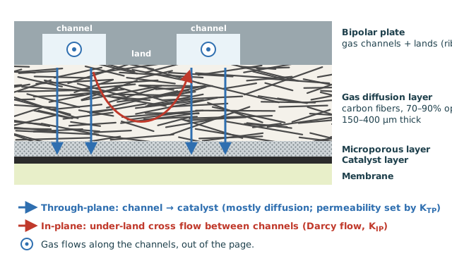
In a PEM fuel cell, the gas diffusion layer (GDL) sits between the bipolar plate and the catalyst layer on both the anode and the cathode. It is a 150 to 400 µm sheet of carbon fibers, usually carbon paper or felt, often treated with PTFE and coated with a microporous layer (MPL) on the catalyst side.
The GDL has four jobs at once:
- Spread the gas from the channels to the catalyst, including the area hidden under the lands.
- Remove product water from the cathode without flooding.
- Conduct electrons and heat between the catalyst layer and the plate.
- Support the membrane and spread the clamping load.
Permeability measures how easily gas flows through it under a pressure difference. It controls the cross flow under the lands, the purge behaviour and how much pressure a stack loses.
Darcy & Forchheimer Flow
\(v = Q/A\) is the Darcy (superficial) velocity, \(L\) the flow length (the thickness for through-plane flow, the land width for under-land flow), \(K\) the permeability in m² and \(\beta\) the Forchheimer inertial coefficient in 1/m.
Darcy's law is the porous-media version of laminar pipe flow: pressure drop rises in proportion to flow. The Forchheimer term adds the extra loss when the gas speeds up and slows down around the fibers at higher flow.
With the Ergun-based β, inertia adds about 2% to the pressure drop at \(Re_K\) = 0.1 and about 10% near 0.5. In a fuel cell GDL, \(Re_K\) is usually below 0.01, so plain Darcy's law is accurate. The Inertial share result above shows this directly.
Through-Plane vs. In-Plane Permeability
Carbon paper fibers lie almost flat in the plane of the sheet. Gas moving in-plane runs along the fibers. Gas moving through-plane has to weave across them. So most papers are anisotropic: in-plane permeability is usually 1.5 to 2 times the through-plane value.
Which one you need depends on the question:
- Through-plane: material specifications, quality control and permeability tests, plus purge and pressure-equalization flow through the MEA.
- In-plane: under-land (under-rib) cross flow between channels, reactant supply to the area under the lands, and water removal.
| Material | ε | t, µm | KIP | KTP |
|---|---|---|---|---|
| Toray TGP-H-060 | 0.84 | 176 | 40.9 – 43.7 | 26.8 |
| SGL 25 BA | 0.71 | 168 | 42.4 – 54.8 | 43.5 |
| AvCarb MGL 370 | 0.80 | 308 | 37.3 – 38.0 | 27.7 |
| Woven carbon cloth | 0.82 | 98 | 11.6 – 13.6 | 9.3 |
K in 10⁻¹² m², computed from 3D images of real samples (Shokri et al., Sci. Rep. 14, 2024). Measured values in the literature are often 2 to 6 times lower, for example 6.6 (through-plane) and 14.4 (in-plane) for Toray TGP-H-060. Expect a wide spread between methods and between production lots.
| Toray datasheet | t, µm | ε | Gas permeability | K (air, 20 °C) |
|---|---|---|---|---|
| TGP-H-060 | 190 | 0.78 | 1,900 | 9.7 × 10⁻¹² m² |
| TGP-H-090 | 280 | 0.78 | 1,700 | 8.7 × 10⁻¹² m² |
Gas permeability in ml·mm/(cm²·h·mmAq), through-plane.
Measuring Permeability
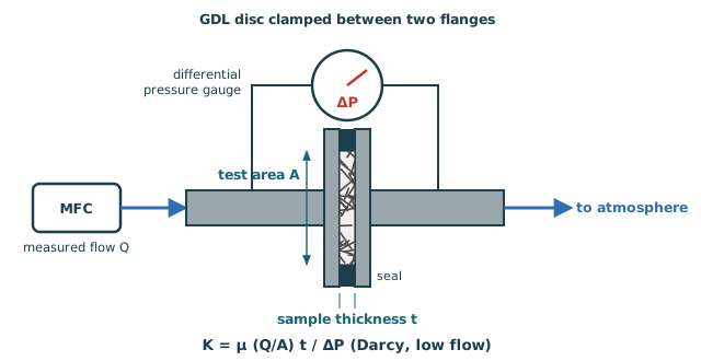
- Cut a disc, measure its thickness and clamp it with a seal around the edge. A 25.4 mm opening gives 5.067 cm².
- Flow dry air or nitrogen at five or more rates and record the steady pressure drop at each.
- Convert flow to Darcy velocity \(v = Q/A\) using the actual flow at the test pressure and temperature.
- Plot \(\Delta P/(t\,v)\) against \(v\). The straight-line fit gives both constants:
The intercept is \(\mu/K\) and the slope is \(\beta\rho\). With one point or a flat line, use Darcy's law alone: \(K = \mu\,v\,t/\Delta P\). The test data calculator above does this fit for you.
Datasheet Permeability Units
GDL suppliers rarely quote permeability in m². The three common formats all come from Darcy's law with room-temperature air:
ml·mm/(cm²·h·mmAq) is flow per area, times thickness, per pressure, which is \(K/\mu\):
The time for 100 cm³ of air to pass through 6.45 cm² (1 in²) at 1.22 kPa:
ASTM D737 flow in ft³/min per ft² at 125 Pa (0.5 inH₂O). Convert the flow to a velocity (1 cfm/ft² = 0.00508 m/s):
Example: Toray TGP-H-060 at 1,900 is K = 9.7 × 10⁻¹² m², a Gurley time of about 0.045 s and a Frazier value of about 70 cfm/ft². Use the converter in the second calculator for any value.
Estimating K from the Fibers
Without measured data, permeability can be estimated from the porosity and the fiber radius \(r_f\). The Tomadakis-Sotirchos model treats the GDL as a random bed of straight fibers and has no fitted constants:
Carbon fibers in most GDLs are 7 to 10 µm in diameter. Porosity follows from the bulk density: \(\varepsilon = 1 - \rho_{bulk}/\rho_{fiber}\), with \(\rho_{fiber} \approx\) 1.8 to 2.0 g/cm³.
| Direction (2D random fibers) | εp | α |
|---|---|---|
| In-plane | 0.11 | 0.521 |
| Through-plane | 0.11 | 0.785 |
εp is the percolation threshold, the porosity below which no open path remains.
- K scales with fiber radius squared: thicker fibers give a more open sheet.
- K rises steeply with porosity, especially near the top of the range.
- The model leaves out binder, PTFE and the MPL, so treat it as a ±2× estimate. Use it for trends, such as the effect of compression, and use measured data for absolute values.
Compression Under the Land
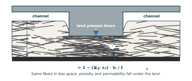
Stacks are clamped so the GDL is compressed by roughly 10 to 30% under the lands. This lowers contact resistance and seals the cell, but the same fibers then fill less space.
Porosity drops modestly, but permeability drops much faster. For carbon paper starting at ε = 0.78, 25% compression lowers porosity to about 0.71. The fiber model then puts permeability at about 40% of its original value, in both directions. See the K vs. Compression graph.
The in-plane permeability under the land is what governs cross flow. Real papers vary: one image-based study found in-plane reductions of only 3 to 33% for Toray TGP-H-060 but 48 to 68% for SGL 25 BA. Use measured compressed-state data when you have it.
Under-Land (Under-Rib) Cross Flow
In a serpentine flow field, neighbouring channel passes are at different pressures because the gas has travelled a long way between them. That pressure difference pushes gas in-plane through the compressed GDL under the land, short-circuiting the channel.
Under-land flow is not all bad. It brings fresh reactant to the catalyst under the land and helps push liquid water out, which is why some designs encourage it on purpose. It can also starve the downstream channel passes and give uneven current density.
\(w\) is the land width, \(t_c\) the compressed thickness and \(\ell\) the land length. Choose In-plane above and Pressure drop → flow to calculate it.
Worked Examples
1 L/min of air at 25 °C (μ = 0.01849 cP) through a 25.4 mm disc (5.067 cm²) of TGP-H-060, 190 µm thick. This is the calculator's Load Example.
- Datasheet: 1,900 × 2.8325 × 10⁻¹⁰ × 1.81 × 10⁻⁵ = K = 9.74 × 10⁻¹² m².
- v = (1 × 10⁻³/60)/(5.067 × 10⁻⁴) = 0.0329 m/s.
- \( \Delta P = \dfrac{\mu\,v\,t}{K} \) = (1.849 × 10⁻⁵)(0.0329)(190 × 10⁻⁶)/(9.74 × 10⁻¹²) = 11.9 Pa.
- The inertial term adds only 0.14%, so this is pure Darcy flow.
Same paper, compressed from 190 to 150 µm under a 1.0 mm land that is 100 mm long. Air at 80 °C (μ = 0.02087 cP) sees a 200 Pa difference between neighbouring channels.
- Compressed porosity: εc = 1 − 0.22 × 190/150 = 0.721.
- The fiber model scales the datasheet value to in-plane at εc: KIP ≈ 7.5 × 10⁻¹² m².
- v = K ΔP/(μ w) = (7.5 × 10⁻¹²)(200)/((2.087 × 10⁻⁵)(0.001)) = 0.072 m/s.
- Q = v × (150 µm × 100 mm) = about 65 mL/min under this one land.
For a single-cell serpentine carrying a few hundred mL/min of air, that is a large share of the flow bypassing the channel.
Frequently Asked Questions
- What is a typical GDL permeability?
- About 5 to 50 × 10⁻¹² m² for uncompressed carbon paper or felt without an MPL. In-plane is usually 1.5 to 2 times through-plane. With an MPL, through-plane values can fall to 10⁻¹⁴ to 10⁻¹³ m².
- How do I convert Toray gas permeability to m²?
- Multiply by 2.8325 × 10⁻¹⁰ and by the air viscosity in Pa·s (1.81 × 10⁻⁵ at 20 °C). TGP-H-060 at 1,900 gives 9.7 × 10⁻¹² m².
- Should I use Darcy or Darcy-Forchheimer?
- Darcy is enough for almost every GDL calculation. Fit the Forchheimer term only when your test reaches high flows and the plot of ΔP/(t v) against v clearly slopes up.
- Does permeability change with temperature or gas?
- No. K is a property of the solid structure. The pressure drop changes because viscosity changes: hydrogen is about half as viscous as air, and air at 80 °C is about 13% more viscous than at 25 °C.
- Why is my measured K lower than the fiber model?
- Binder, PTFE and an MPL all block flow paths that the fiber model assumes are open. Edge sealing that compresses the sample, or using standard instead of actual flow, also lowers the result.
- What about liquid water in the GDL?
- Water fills some pores and lowers the gas permeability. Two-phase models multiply K by a relative permeability, often taken as (1 − s)³, where s is the liquid saturation.
- Where else are pressure drops calculated in a fuel cell system?
- Packed beds such as cathode air filters, desulfurizers, reformer catalysts and metal hydride stores use the Ergun equation. See the packed bed pressure drop calculator.