Optional: enter any two of heat duty Q, overall coefficient U and area A to get the third.
What Is LMTD?
LMTD stands for Log Mean Temperature Difference. It is the average temperature difference that drives heat from the hot fluid to the cold fluid in a heat exchanger.
The temperature difference is not the same everywhere in an exchanger. It is large where the hot fluid meets cold fluid and small where the two have nearly matched. Heat transfer depends on that difference at every point, so the exchanger needs one number that represents the whole length. For steady flow with constant properties, that number is the logarithmic mean of the two end differences.
With the LMTD known, the basic sizing equation is
where \(Q\) is the heat duty, \(U\) the overall heat transfer coefficient, \(A\) the heat transfer area, \(F\) the correction factor for the flow arrangement and \(\Delta T_{lm,\,cf}\) the counterflow LMTD.
The LMTD Formula
\(T\) is the hot fluid and \(t\) the cold fluid. Subscript 1 is an inlet and 2 an outlet. It does not matter which end you call ΔT₁; the formula gives the same answer either way.
When ΔT₁ = ΔT₂ the formula becomes 0/0. The limit is simply that common value, which happens in counterflow when both fluids have the same heat capacity rate.
Take a small slice of the exchanger with area \(dA\). The heat crossing it is \(dQ = U\,\Delta T\,dA\). The hot fluid loses that heat and the cold fluid gains it, so the local difference changes by
where \(C = \dot m\,c_p\) is each fluid's heat capacity rate (minus sign for counterflow, plus for parallel). Substituting \(dQ\) and integrating from one end to the other gives a logarithm:
The heat balance gives \(1/C_h \pm 1/C_c = (\Delta T_1 - \Delta T_2)/Q\). Combining the two results gives \(Q = U A\,\Delta T_{lm}\). The local difference falls exponentially along the length, which the Local ΔT graph above shows.
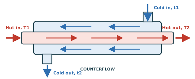
Heat Exchanger Flow Arrangements
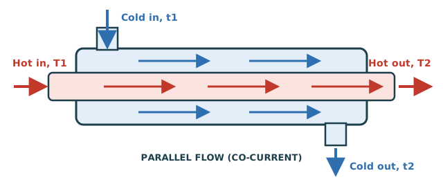
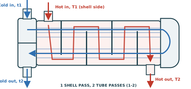
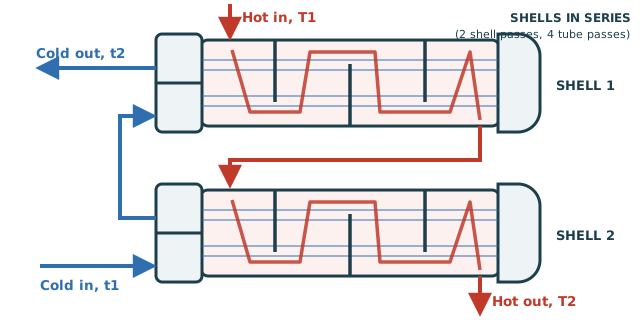
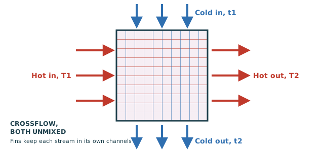
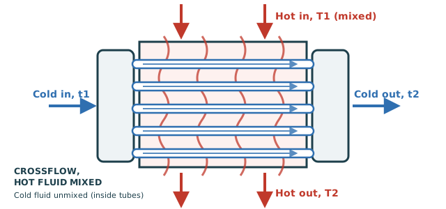
The Correction Factor F
Only pure counterflow and parallel flow have a simple LMTD. For every other arrangement the counterflow LMTD is multiplied by a correction factor \(F \le 1\). F depends on two temperature ratios:
P is how far the cold fluid is heated, as a fraction of the most it could be. R is the ratio of the two heat capacity rates.
This is Bowman's equation. For R = 1 use the limit \(F = \dfrac{\sqrt2\,P/(1-P)}{\ln\!\left[\dfrac{2-P(2-\sqrt2)}{2-P(2+\sqrt2)}\right]}\).
For any arrangement, F is the ratio of the number of transfer units (NTU) that pure counterflow needs to reach the given P and R, to the NTU this arrangement needs:
This one method gives F for any number of shell passes and for both kinds of crossflow. For one shell pass it reproduces Bowman's equation exactly.
- Keep F ≥ 0.75 to 0.80. Below that the F curve is steep, so a small error in temperatures means a large error in area.
- If F is too low, add a shell pass (or use shells in series) before adding area.
- Each curve on the F chart ends at a maximum P. Past it, that arrangement cannot reach the outlet temperatures at any size.
- If one fluid stays at constant temperature (condensing or boiling), F = 1 for every arrangement.
Effectiveness & NTU
The effectiveness–NTU method describes the same physics as LMTD. It is more convenient when the outlet temperatures are unknown, for example when rating an existing exchanger.
When the outlet temperatures are known, use LMTD. When you know the size and need the outlets, use ε–NTU. This calculator reports both: ε comes straight from the temperatures, and NTU is solved for the chosen arrangement.
| Arrangement | ε(NTU, Cr) |
|---|---|
| Counterflow | \( \dfrac{1-e^{-NTU(1-C_r)}}{1-C_r\,e^{-NTU(1-C_r)}} \) |
| Parallel flow | \( \dfrac{1-e^{-NTU(1+C_r)}}{1+C_r} \) |
| 1 shell pass | \( 2\left[1+C_r+\sqrt{1+C_r^2}\,\dfrac{1+e^{-NTU\sqrt{1+C_r^2}}}{1-e^{-NTU\sqrt{1+C_r^2}}}\right]^{-1} \) |
| Crossflow, Cmax mixed | \( \dfrac{1}{C_r}\left(1-e^{-C_r\left(1-e^{-NTU}\right)}\right) \) |
| Crossflow, Cmin mixed | \( 1-e^{-\frac{1}{C_r}\left(1-e^{-C_r NTU}\right)} \) |
| Crossflow, both unmixed | \( 1-\exp\!\left[\dfrac{NTU^{0.22}}{C_r}\left(e^{-C_r NTU^{0.78}}-1\right)\right] \) (approx.) |
N shell passes in series use the 1-shell relation for each shell (NTU/N each) and combine them as counterflow stages.
Temperature Cross & Approach
Approach is the smallest temperature difference anywhere in the exchanger. In counterflow it is the smaller of ΔT₁ and ΔT₂. Smaller approach means more heat recovered, but area grows quickly as the approach shrinks.
A temperature cross means the cold outlet is hotter than the hot outlet (t₂ > T₂).
- Counterflow handles a cross easily.
- Parallel flow can never produce one. The calculator reports it as impossible.
- A 1-2 shell and tube can only tolerate a small cross. Past that, F drops sharply and soon no area is enough. Add shells in series.
Worked Example: Sizing an Oil Cooler
Hot oil is cooled from 250 °F to 150 °F by water heated from 70 °F to 110 °F in a 1-2 shell and tube exchanger. The duty is 1,000,000 BTU/hr and U is 75 BTU/hr·ft²·°F. (This is the calculator's Load Example.)
- Counterflow ends: ΔT₁ = 250 − 110 = 140 °F, ΔT₂ = 150 − 70 = 80 °F.
- \( \Delta T_{lm} = \dfrac{140 - 80}{\ln(140/80)} = 107.22\ \text{°F} \)
- P = (110 − 70)/(250 − 70) = 0.2222, R = (250 − 150)/(110 − 70) = 2.5
- Bowman's equation gives F = 0.9380, so the corrected LMTD = 0.9380 × 107.22 = 100.57 °F.
- \( A = \dfrac{Q}{U\,F\,\Delta T_{lm}} = \dfrac{1{,}000{,}000}{75 \times 100.57} = 132.6\ \text{ft}^2 \)
| Arrangement (same temperatures) | F | Effective LMTD |
|---|---|---|
| Counterflow | 1.000 | 107.22 °F |
| Shell & tube, 2 shell passes | 0.985 | 105.64 °F |
| Crossflow, both unmixed | 0.951 | 101.92 °F |
| Shell & tube, 1 shell pass | 0.938 | 100.57 °F |
| Parallel flow | 0.868 | 93.08 °F |
Same duty and U: parallel flow would need 1,000,000/(75 × 93.08) = 143.3 ft², about 15% more area than counterflow.
Typical Overall Heat Transfer Coefficients
| Service | U, W/m²·K | U, BTU/hr·ft²·°F |
|---|---|---|
| Water to water | 850 – 1,700 | 150 – 300 |
| Condensing steam to water | 1,000 – 3,500 | 175 – 600 |
| Light organics to water | 350 – 900 | 60 – 160 |
| Condensing refrigerant to water | 300 – 1,000 | 50 – 175 |
| Water to oil | 100 – 350 | 20 – 60 |
| Water to air, finned tubes (air-side area) | 25 – 50 | 4 – 9 |
| Gas to gas | 10 – 40 | 2 – 7 |
Order-of-magnitude ranges for early sizing only. Real values depend on velocities, viscosity, fouling, geometry and which area U is based on. 1 BTU/hr·ft²·°F = 5.678 W/m²·K.
Common Mistakes
- Pairing the wrong ends. Counterflow pairs hot inlet with cold outlet. Parallel flow pairs the two inlets.
- Using the arithmetic mean. It is always larger than the LMTD, so it undersizes the exchanger. The error is about 4% when one end difference is twice the other, and grows quickly beyond that.
- Forgetting F. A 1-2 shell and tube with the counterflow LMTD and no F can be undersized by 10–25%.
- Mixing units. A temperature difference of 1 °C equals 1 K, and 1 °F equals 1 °R. Keep U, A and Q in one consistent system.
- One LMTD across a phase change. A condenser that also subcools has two zones with different temperature profiles. Size each zone separately.
Frequently Asked Questions
- What is the full form of LMTD?
- Log Mean Temperature Difference: the logarithmic average of the hot-to-cold temperature difference at the two ends of a heat exchanger.
- What is the LMTD formula?
- LMTD = (ΔT₁ − ΔT₂) / ln(ΔT₁/ΔT₂). For counterflow, ΔT₁ = T₁ − t₂ and ΔT₂ = T₂ − t₁. For parallel flow, ΔT₁ = T₁ − t₁ and ΔT₂ = T₂ − t₂.
- Why is it a log mean and not an average?
- The local temperature difference falls exponentially along the exchanger, and the true average of an exponential curve is the logarithmic mean. The arithmetic mean always comes out higher.
- Can the LMTD be negative or zero?
- No. Both end differences must be positive for heat to flow from hot to cold everywhere. A zero or negative end difference means the temperatures you entered are impossible for that arrangement.
- Do I use °C or K, °F or °R?
- Either. Only differences enter the formula, and a difference of 1 °C equals 1 K (1 °F equals 1 °R). The calculator gives the same LMTD in both.
- What does F = 0.7 mean?
- The arrangement transfers heat like a counterflow exchanger with only 70% of the driving force, so it needs about 1/0.7 = 1.43 times the area. More importantly, it is on the steep part of its curve. Add shell passes instead.
- What LMTD do I use for a condenser or boiler?
- If one side stays at a constant temperature, the flow pattern no longer matters: F = 1, and the counterflow and parallel LMTDs are equal.