- NASA-RP-1228: Barrett, R. T. (1990). Fastener Design Manual. Thread pull-out, torque-preload, combined loading. Download PDF (5.1 MB).
- Machinery’s Handbook: Industrial Press. Length of thread engagement and the shear areas of internal and external threads.
- ASME B1.1: Unified Inch Screw Threads. Defines UN, UNC, UNF thread geometry, the basic profile and tensile stress areas.
- AS8879 (SAE): Screw Threads — UNJ Profile, Inch Controlled Radius Root with Increased Minor Diameter. Aerospace UNJ/UNJF thread standard.
- ISO 68-1 and ISO 898-1: Basic profile of ISO metric screw threads, and Mechanical Properties of Fasteners Made of Carbon Steel and Alloy Steel. Metric stress areas and property classes.
- Bickford, J.H.: An Introduction to the Design and Behavior of Bolted Joints, 3rd Ed. Marcel Dekker.
- MMPDS-10 / MMPDS-13: Metallic Materials Properties Development and Standardization. Shear and tensile strengths of aerospace alloys.
- Nominal dimensions. The strip areas use the basic thread profile. The tolerance class of the real threads, the finish and the fit can lower them. Add a fitting factor, or check the actual limits, for a critical joint.
- Shear strength. Where a material has no published Fsu in the presets, it is taken as 0.6 Ftu. That is an estimate, and heat treatment, temper and form all move it.
- For informational use only. This calculator is provided as an engineering aid. Results must be verified by a qualified engineer before use in any safety-critical or flight application. KasperCalc assumes no liability for design decisions made using these results.
Internal Thread Stress Calculator: Nut and Tapped Hole Thread Stripping and Engagement Length, AS8879 / UNC / UNF / Metric
Internal Thread Stress Calculator | AS8879 / UNC / UNF / Metric
For the threads of a nut or tapped hole. For the bolt, its torque and its preload, use the External Thread Stress Calculator.
Enter the major diameter and TPI of the thread pair. The pitch diameter and the bolt’s stress area are calculated for you.
Extra custom threads – override the calculated values
Leave a box blank to use the calculated value. The strip areas assume a basic 60° thread form, so Acme, buttress and other forms are outside this page.
F_su is 0.6 × F_tu unless the preset lists a published value (6061-T6 and 7075-T6). Choose Custom to enter one from MMPDS or your material spec.
Tapped holes are commonly cut to 65–75%. A nut made to the basic minor diameter is about 83%. The internal minor diameter K for the chosen thread is shown under Thread Selection.
P is the axial force through the thread: the bolt preload, or the preload plus the external load. The External Thread Stress Calculator turns a torque into a preload.
The other method is always shown beside the result as a cross-check.
Fill in inputs on the left and click Calculate.
| Failure Mode | Area (in²) | Stress at Load (psi) | Capacity (lb) | MS |
|---|
Parametric: Strip Load vs Engagement Length
Capacity of each thread at other engagement lengths, with the bolt’s own strength for comparison. Selected L highlighted ◀
| L (in) | L/d | Internal (lb) | External (lb) | Weakest | MS |
|---|
Overview
A bolt in a nut or tapped hole can fail three ways under axial load. The bolt can break in tension. The threads of the nut or tapped part can strip. The threads of the bolt can strip. The first is a ductile failure that gives some warning. The other two are sudden, and the first of them usually ruins the tapped part as well.
This page checks the internal thread of the nut or tapped hole together with the external thread it mates with. For each mode it finds the load that causes failure, the margin of safety at your load, and which one fails first. It also gives the engagement length that makes the bolt the weakest link.
The bolt’s torque, preload and tensile stress are on the External Thread Stress Calculator. Enter its preload here as the applied load. The thread tables, material presets and units are the same on both pages. Thread forms follow ASME B1.1, AS8879 and ISO 68-1 / ISO 898-1.
Thread Geometry & Percent Thread
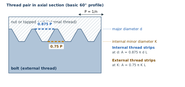
The strip areas follow from the basic 60° thread profile. With \(n\) threads per unit length, the pitch is \(P = 1/n\). The pitch diameter of the basic profile is:
The internal thread is cut with a tap drill that leaves a minor diameter \(K\). The percent thread says how much of the full thread depth that leaves. The chart convention is that a 100% thread is cut to a depth of \(0.6495\,P\) on each side:
- The basic minor diameter of an internal thread, \(d - 1.0825\,P\), is an 83% thread.
- Tapped holes are commonly cut to 65–75% because the last few percent cost a lot of tap torque and add little strength.
- The internal crest cannot cut deeper than the external root, \(d - 1.2269\,P\), which is about a 94% thread. The page holds \(K\) at that limit.
The bolt’s tensile stress area \(A_s\) is the table value for the chosen thread, the same one the External Thread Stress Calculator uses.
Internal Thread (Nut or Tapped Hole) Strip
The internal thread strips when its teeth shear off at their roots, along the cylinder through the bolt’s major diameter \(d\). Each tooth is as wide at the root as the thread pitch less the root flat. Over the engaged length \(L\) there are \(nL\) teeth, so the shear area is:
For the basic profile that is \(A_n = 0.875\,\pi\,d\,L\). It does not depend on the percent thread, because the root of the tooth is where the tooth is widest whatever the tap drill. The load that strips it is:
\(F_{su,int}\) is the shear ultimate strength of the nut or tapped part.
External Thread (Bolt) Strip
The bolt’s thread strips along the cylinder at the internal thread’s minor diameter \(K\), where the teeth of the bolt meet the crests of the nut. The width of a bolt tooth at that cylinder depends on how far the flanks have spread, so the percent thread enters here:
At the basic minor diameter that is \(A_e = 0.75\,\pi\,K\,L\). A shallower tapped hole has a larger \(K\), a smaller overlap \(d_m - K\), and so a smaller area. At 0% thread only the crest flat of the bolt, an eighth of the pitch, is left to shear.
\(F_{su,ext}\) is the shear ultimate strength of the bolt. Both areas are the form given for the length of thread engagement in Machinery’s Handbook, with the nominal dimensions of the basic profile in place of the class limits.
Margin, Weakest Link & Engagement Needed
The bolt’s own tensile capacity is set by the stress area. The three ultimate capacities are compared, and the smallest is the mode that fails first:
The strip areas grow in proportion to \(L\), and the bolt’s strength does not. The engagement at which a thread matches the bolt’s ultimate load is:
The longer of the two requirements, internal or external, is the engagement to specify. It rises in proportion to the strength of the bolt over the strength of the weaker part, which is why a steel bolt in aluminum needs a much deeper hole than a steel bolt in a steel nut. Yield is shown for the bolt only. Thread stripping has no useful yield, so it is judged at ultimate.
NASA-RP-1228 Pull-Out (Cross-Check)
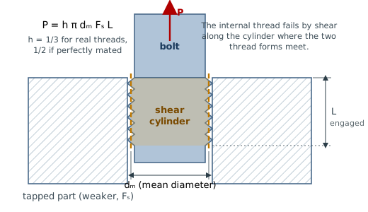
NASA-RP-1228 (Fastener Design Manual) sizes the engagement from one empirical factor on the cylinder at the mean diameter:
with dM the mean diameter of the tapped hole (the pitch diameter is used if blank), Fs the shear strength of the member, L the length of engagement, and h the thread-mismatch factor. If the threads mated perfectly h would be 1/2. The manual recommends 1/3 to allow for the mismatch of real threads.
This is the same check as the thread pull-out on the External Thread Stress Calculator. It is deliberately the more conservative method. It uses the pitch-diameter cylinder, where the tooth is half a pitch wide, rather than the tooth root, and then takes a third of that. For the same material it gives a bit over a third of the shear-area strength, so it asks for a much longer engagement. Choose it when you want that margin built in, or when the thread is not a close fit.
Source: NASA-RP-1228, Fastener Design Manual, the pull-out formula (PDF, 5.1 MB), a public-domain NASA report mirrored here.
AS8879 Thread Note
AS8879 (formerly MIL-S-8879) specifies UNJ (coarse) and UNJF (fine) aerospace threads. These differ from standard UN threads by having a controlled radius root on the external thread, which significantly improves fatigue life by reducing stress concentration at the thread root. AS8879 threads are the preferred aerospace thread form for structural fasteners per NAS and military standards.
The controlled root radius is on the bolt. The internal thread that mates with it is a standard internal thread, so the strip areas on this page use the same basic profile for UNJ and for UN threads.
What the Method Leaves Out
- Nominal dimensions. The areas use the basic profile. The pitch diameter allowance and tolerance of the thread class take material off the teeth, and the effect is larger on fine threads. Use a fitting factor above 1.0, or the NASA method, where that matters.
- Even load sharing. The load is spread over all the engaged teeth. In a real nut the first teeth carry more than their share, so a very long engagement gains less than the arithmetic suggests.
- Shear strength. Fsu is taken as 0.6 Ftu unless a published value is listed or entered. Use the MMPDS value for the material and temper where you have it.
- Engaged threads only. Count full threads. Leave out the chamfer, the countersink and the thread run-out at the bottom of a blind hole.
- The tapped part itself. Wall thickness, edge distance and the strength of the boss around the hole are not checked. A thin wall can spread (dilate) and strip at a load below the figure here.
- Inserts and other thread forms. Helical-coil and key-locking inserts, Acme, buttress and rolled threads are outside this page.
- Other loads. Torsion, bending, shear across the thread and fatigue are not included.
Worked Example: A 3/8″ A-286 Bolt in 6061-T6
The 3/8-24 UNJF A-286 bolt of the External Thread Stress Calculator example carries its 3,419 lb preload. It threads 9/16″ (1.5D) into a 6061-T6 part, tapped to a 75% thread. A-286 has Ftu = 145 ksi and Fty = 95 ksi in the presets, so Fsu = 0.6 × 145 = 87 ksi. 6061-T6 has Fsu = 27 ksi. Load this example into the calculator.
The bolt breaks first, at 12,688 lb, and the aluminum threads would carry 23% more than that. The two margins on the bolt match the External Thread Stress Calculator example, as they should.
The aluminum thread sets the length. The NASA-RP-1228 method, with h = 1/3, gives 5,533 lb for the same internal thread (MS +0.62) and asks for 1.29″, 3.4 diameters. The truth for a real tapped hole lies between the two, which is why the fitting factor and the limits listed above matter.
Verification
The strip areas (js/fastener-math.js) run in automated tests against hand calculations:
| Case | By hand | This page |
|---|---|---|
| 3/8-24 UNJF, 75% thread, external area per inch | π(0.334405)[0.5 + 0.57735(24)(0.3479 − 0.334405)] | 0.7217 in²/in |
| Same thread, internal area per inch | π(0.375)[0.5 + 0.57735(24)(0.375 − 0.3479)] | 1.0314 in²/in |
| Basic minor diameter (83.3% thread) | 0.75 π K L and 0.875 π d L | 0.7500 and 0.8750 |
| Inches against millimetres | areas scale by 25.4² | agree to 1e-9 |
The basic-profile factors 0.75 and 0.875 are the textbook values for a 60° thread. The page’s numbers follow from the same expressions with the percent thread in place of the basic minor diameter.