Hertz Contact Stress Calculator: Spheres, Cylinders, Crossed Cylinders, Rigid Cone and Knife Edge
Contact pressure, contact size, approach and the stresses below the surface for nine classic contact cases | Hertz theory, Johnson’s Contact Mechanics & AFFDL-TR-69-42 Chapter 11
Normal load, pressing the bodies together. For the line cases the load is spread evenly over the contact length L.
Allowable contact pressure (optional)
A static contact-pressure limit from your own data or a standard. ISO 76 uses 4,200 MPa (609 ksi) for ball bearings and 4,000 MPa (580 ksi) for roller bearings.
Results update as you type.
| Check | Applied | Allowable | MS |
|---|
Principal stresses on the load axis, with the maximum shear and von Mises stress. The red dots mark their peaks, which sit below the surface.
Overview: What Hertz Contact Describes
Press a ball against a plate and, in theory, they touch at a single point. Under load both surfaces flatten, and the force spreads over a small patch: a circle for a ball, a narrow strip for a roller, an ellipse for two crossed cylinders. Heinrich Hertz worked out the size of that patch and the pressure across it in 1882, and his solution still underpins the design of ball and roller bearings, gears, cams and followers, wheels on rails, pivots, knife-edge supports and indenters.
The striking result is how high the pressure gets. The patch is tiny compared with the bodies, so even modest loads give contact pressures of hundreds of ksi. Ordinary materials survive it because the material under the patch is squeezed from every side at once, and the stress that does the damage is not the surface pressure but a shear stress that peaks below the surface.
Hertz theory rests on a few assumptions, and it is worth knowing where they stop holding:
- Both bodies are linear elastic and isotropic. Once either one yields, the theory over-predicts the pressure.
- The contact patch is small compared with the radii of curvature and with the size of each body, so each can be treated as an elastic half-space.
- The surfaces are smooth and frictionless: only normal pressure is transmitted. Sliding friction adds a surface shear and moves the peak stress toward the surface.
- The profiles near the contact are smooth and can be approximated by a quadratic (the radius of curvature is constant across the patch).
Two Numbers Describe Any Pair: E* and R
Every case on this page reduces to an equivalent contact between a single elastic body and a rigid one. The two materials collapse into one contact modulus, and the two curvatures into one relative radius:
The sign is plus when both surfaces are convex and minus when one wraps the other (a ball in a socket, a roller in a groove). A flat plate has an infinite radius, so it drops out. A rigid body has an infinite modulus, so its term drops out of E*. The cases on this page:
| Case | Contact | Relative radius R |
|---|---|---|
| Sphere on sphere | circle | D₁D₂ / 2(D₁ + D₂) |
| Sphere in a socket | circle | D₁D₂ / 2(D₁ − D₂), D₁ the socket |
| Sphere on a flat | circle | D / 2 |
| Parallel cylinders | strip | D₁D₂ / 2(D₁ + D₂) |
| Cylinder in a groove | strip | D₁D₂ / 2(D₁ − D₂), D₁ the groove |
| Cylinder on a flat | strip | D / 2 |
| Crossed cylinders | ellipse | two curvatures, 1/D₁ and 1/D₂ (card 05) |
| Rigid knife edge | line | — (Flamant, card 08) |
| Rigid cone | circle | — (Sneddon, card 08) |
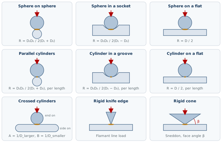 Fig. 1 — The nine cases on this page and the relative radius each one reduces to
The conforming cases are the reason ball sockets and grooved tracks are used: as D₂ approaches D₁, R grows without limit and the pressure falls. The patch then stops being small compared with the radii, and Hertz theory stops applying.
Point Contact: Spheres
Two spheres (or a sphere and a flat or socket) touch over a circle of radius a. The pressure is a hemisphere over that circle, highest at the centre and falling to zero at the edge:
δ is the mutual approach of two points far from the contact, which is the elastic “give” of the joint. The cube roots matter in practice. Doubling the load raises the peak pressure by only 21/3 = 1.26, so a design with a negative margin needs a lot more geometry, not a little: halving the pressure needs eight times less load or a much larger radius.
AFFDL-TR-69-42 Table 11-1 writes the same results with the constants evaluated: a = 0.721 [P (D₁D₂/(D₁+D₂)) (k₁+k₂)]1/3 with k = (1−ν²)/E, and p₀ = 0.918 [P ((D₁+D₂)/D₁D₂)² / (k₁+k₂)²]1/3.
Line Contact: Cylinders
Cylinders with parallel axes touch along a strip of width 2b. With w the load per unit length, the pressure across the strip is a half-ellipse:
Here the dependence is a square root, so load matters more than in point contact: doubling w raises p₀ by √2. Unlike the sphere case, the approach of two cylinders is not fixed by the contact alone. For a half-space it grows without limit, so it depends on the size and support of each body. The page leaves it blank rather than quote a number that depends on geometry it does not know.
Real rollers are not infinitely long. At the ends of a straight roller the pressure spikes (edge loading), which is why bearing rollers are crowned or end-relieved. The uniform-load result here is the value away from the ends.
Elliptical Contact: Crossed Cylinders
When the curvatures differ in the two directions, the gap between the surfaces is \(h = Ax^2 + By^2\) and the contact is an ellipse with semi-axes a ≥ b. For cylinders of diameter D₁ and D₂ crossed at 90°, A = 1/Dlarger and B = 1/Dsmaller. The pressure is a semi-ellipsoid, and the ellipse’s eccentricity e = √(1 − b²/a²) is set by the curvature ratio through the complete elliptic integrals K(e) and E(e):
The page solves the first equation for e numerically and evaluates K and E exactly by the arithmetic-geometric mean, so the result holds at any diameter ratio. AFFDL-TR-69-42 and Roark tabulate the same solution as coefficients against the curvature ratio; for equal diameters the ellipse becomes a circle and the result reduces to card 03 with R = D/2.
Why Failure Starts Below the Surface
At the centre of the contact, all three principal stresses are compressive and nearly equal, so the shear there is small. Going down, the lateral stresses fall off faster than the vertical one, the gap between them opens, and the shear stress rises to a peak below the surface before dying away. On the load axis of a circular contact (Johnson, eq. 3.45):
| ν = 0.3 | Peak shear | Depth | p₀ at first yield (von Mises) |
|---|---|---|---|
| Circular (sphere) | 0.31 p₀ | 0.48 a | 1.60 Fty |
| Line (cylinder) | 0.30 p₀ | 0.79 b | 1.79 Fty |
| Elliptical | 0.30–0.33 p₀ | between | about 1.6–1.8 Fty |
This is why rolling-contact fatigue shows up as spalling: cracks start at the depth of peak shear, run parallel to the surface, and eventually lift out a flake. It is also why case-hardened parts need a case deep enough to cover that depth with margin. For elliptical contacts the page integrates the Boussinesq point-load solution over the pressure distribution numerically; tests confirm it reproduces the closed-form circular result to four decimal places.
The one tensile stress in a circular contact is radial, at the edge of the patch, equal to (1 − 2ν) p₀ / 3. It is small, but in brittle materials such as glass, ceramics and carbides it causes the classic Hertzian ring crack before anything happens below the surface.
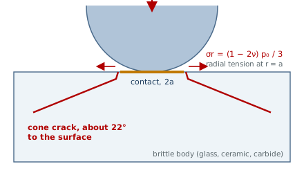 Fig. 4 — The ring crack starts in the radial tension just outside the contact and grows into a shallow cone
Allowables: Yield, Static Ratings and Empirical Limits
First yield. Enter a yield strength for either body and the page compares the peak von Mises stress in that body with it. Because p₀ grows as P1/3 for point contact and P1/2 for line contact, it also reports the load at which yield begins. A margin on stress of +0.36 is a margin on load of (1.36)³ − 1 = +1.5 for a ball. First yield is a conservative limit, because the yielded zone is small and fully surrounded by elastic material. Real parts tolerate a good deal more before any damage is visible, which is why contact allowables are usually set by permanent deformation rather than by first yield.
Static load ratings. For rolling bearings, ISO 76 sets the static rating at the load giving a contact pressure of 4,200 MPa (609 ksi) at the most heavily loaded ball, 4,600 MPa for self-aligning ball bearings, and 4,000 MPa (580 ksi) for rollers. At those pressures the combined permanent deformation of the ball and raceway is about 0.0001 of the ball diameter. Enter such a figure as the allowable contact pressure.
Empirical limits (AFFDL-TR-69-42, §11.7). For a steel cylinder on a flat steel plate under static load, Table 11-2 gives an allowable load per inch of wa = [(Fcy − 13,000)/20,000] × 600 D for D < 25 in. For two equal steel spheres of hardness Rc 64–66, the crushing load is P = 1960 (8D)1.75. The page shows these checks when the case matches, reading the plate’s yield entry as Fcy.
Sharp Indenters: Rigid Cone and Knife Edge
A rigid cone pressed into a flat plate (Sneddon, 1965), with β the angle between the cone face and the surface:
The mean pressure does not depend on the load at all, only on the cone angle and the plate’s modulus, and the pressure is logarithmically infinite at the tip. A real cone either has a rounded tip or yields the plate locally, which is the basis of hardness testing. Only part of δ is contact depth: the surface sinks in around the cone, and the contact edge sits at 2δ/π below the original surface.
A rigid knife edge carrying w per unit length is the Flamant line-load problem. The stress field is purely radial from the edge, and at a point Q at distance r and angle θ from the load line:
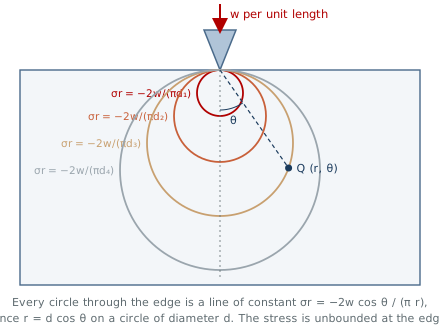 Fig. 5 — Contours of constant radial stress under a knife edge
The stress is constant on circles that pass through the edge and is unbounded at the edge itself, so a knife edge must be checked a finite distance away (a radius equal to the edge’s actual tip radius is a reasonable choice) or treated as a cylinder of that radius on a flat.
When to Distrust the Numbers
- Conforming contacts. In a socket or groove with D₂ close to D₁, the patch becomes a sizable fraction of the radius and Hertz theory over-predicts the pressure. Keep a/R below about 0.1.
- Thin parts. The half-space assumption needs each body to be several times thicker than the contact width; a thin plate or a hollow roller is stiffer locally and sees higher pressure.
- Friction and sliding. A traction coefficient above about 0.3 moves the peak shear to the surface.
- Plastics. Nylon, acetal, PEEK and UHMW polyethylene are in the material list with typical room temperature moduli. A plastic is not linear elastic. Its modulus falls with temperature, moisture and time under load, so the real contact patch is larger and the pressure lower than shown. Treat the result as a first estimate, and use the supplier’s modulus at your temperature as a custom value.
- Plasticity. Above first yield, the elastic pressure is an upper bound; the real pressure flattens toward about 3 Fty under a fully plastic indentation.
- Edges and misalignment. Roller ends, a misaligned shaft or a crown that is too small all concentrate the load beyond the uniform line-contact value.
Worked Example: A Bearing Ball on a Flat Plate
A 1/2″ diameter 52100 steel ball is pressed against a flat plate of the same steel with a load of 50 lbf. For illustration, both are taken to have Fty = 290 ksi, a representative value for through-hardened bearing steel. Both have E = 29.5 × 10⁶ psi and ν = 0.30. Load this example into the calculator.
The contact is under 0.02″ across and the ball and plate approach each other by less than three ten-thousandths of an inch, yet the pressure is 344 ksi. If the load were raised to 126 lbf, the contact would grow to a = 0.0113″ and first yield would start about 0.005″ below the surface, not at it. The edge of the contact sees a radial tension of (1 − 0.6)/3 × 343.9 = 45.9 ksi, harmless in steel but enough to crack glass. Against the ISO 76 static limit of 609 ksi for ball bearings, the margin on pressure is +0.77.
Verification
The calculation engine (js/hertz-math.js) is run in automated tests against Johnson’s published results and against the fitted coefficients of AFFDL-TR-69-42 Table 11-1.
| Case | Reference | This page |
|---|---|---|
| Circular contact: peak shear, depth (ν = 0.3) | 0.31 p₀ at 0.48a (Johnson) | 0.310 p₀ at 0.481a |
| Line contact: peak shear, depth (ν = 0.3) | 0.30 p₀ at 0.786b (Johnson) | 0.300 p₀ at 0.786b |
| p₀ at first yield, circle / line (von Mises) | 1.60 / 1.79 Fty | 1.61 / 1.79 Fty |
| Crossed cylinders, 1″ and 1/2″ steel, 1,000 lbf: a, b, p₀ | 0.0326, 0.0206 in, 710,168 psi (AFFDL Table 11-1 fitted coefficients) | 0.0324, 0.0204 in, 720,932 psi (exact elliptic integrals) |
References
- Hertz, H. (1882). “Über die Berührung fester elastischer Körper.” Journal für die reine und angewandte Mathematik, 92, 156–171. The original solution.
- Johnson, K. L. (1985). Contact Mechanics. Cambridge University Press. Chapters 3 and 4 (Hertz theory, subsurface stresses, elliptical contact) and chapter 6 (onset of yield).
- Timoshenko, S. P. and Goodier, J. N. (1970). Theory of Elasticity, 3rd ed. McGraw-Hill. §§138–140, the Boussinesq problem and the pressure between two bodies in contact.
- Young, W. C., Budynas, R. G. and Sadegh, A. M. (2020). Roark’s Formulas for Stress and Strain, 9th ed. McGraw-Hill. Table 14.1, formulas for stress and strain due to pressure on or between elastic bodies.
- Boresi, A. P. and Schmidt, R. J. (2003). Advanced Mechanics of Materials, 6th ed. Wiley. Chapter 17, contact stresses.
- Air Force Flight Dynamics Laboratory (1986). Stress Analysis Manual, AFFDL-TR-69-42. Chapter 11, bearing stresses: Table 11-1 and the empirical allowables of §11.7. Open Chapter 11.
- Thomas, H. R. and Hoersch, V. A. (1930). “Stresses due to the pressure of one elastic solid upon another.” University of Illinois Engineering Experiment Station Bulletin 212. Subsurface stresses for elliptical contacts.
- Sneddon, I. N. (1965). “The relation between load and penetration in the axisymmetric Boussinesq problem for a punch of arbitrary profile.” International Journal of Engineering Science, 3, 47–57. The rigid cone.
- Flamant, A. (1892). “Sur la répartition des pressions dans un solide rectangulaire chargé transversalement.” Comptes Rendus, 114, 1465–1468. The line load on a half-space.
- ISO 76:2006. Rolling bearings — Static load ratings. The 4,000–4,600 MPa contact-pressure limits.
- Harris, T. A. and Kotzalas, M. N. (2007). Rolling Bearing Analysis, 5th ed. CRC Press. Contact stress in bearing practice, crowning and edge stresses.